C
82
C
52
C
42
C
82
19 20
21 22
1
8
10
6
6
7
3
2
S
A
4
5
8
9
21
INSTALLER
USER
MAINTENANCE TECHNICIAN
TECHNICAL DATA
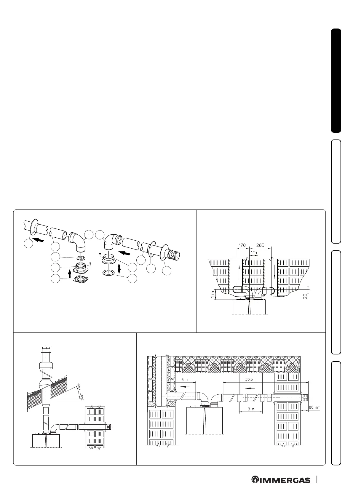
e kit includes:
N°1 - Exhaust gasket (1)
N°1 - Flange gasket (2)
N°1 - Female intake ange (3)
N°1 - Female exhaust ange (4)
N°1 - Anti-pulse plate (5)
N°2 - 90° bends Ø 80 (6)
N°1 - Intake terminal Ø 80 (7)
N°2 - Internal wall sealing plates (8)
N°1 - External wall sealing plate (9)
N°1 - Exhaust pipe Ø 80 (10)
• Assembly of separator kit Ø 80/80 (Fig. 19).
install the ange (4) on the central hole of the boiler inserting
the gasket (1) and tighten using the hex head and at tip screws
contained in the kit, insert the anti-pulse plate up to the stop (5).
Remove the at ange present in the lateral hole with respect to
the central one (according to needs) and replace it with the ange
(3), positioning the gasket (2) already present in the boiler and
tighten using the supplied self-threading screws. Fit the male end
(smooth) to the bends (6) in the female end of the anges (3 and
4). Fit the intake terminal (7) with the male section (smooth) in
the female section of the bend (6) up to the stop, ensuring that
the internal and external wall sealing plates are tted. Fit the
exhaust pipe (10) with the male end (smooth) in the female end
of the bend (6) up to the stop, making sure that the internal wall
sealing plate has been tted, this will ensure sealing and joining
of the kit elements.
• Installation clearances (Fig. 20).
e minimum installation clearance measurements of the Ø
80/80 separator terminal kit have been stated in some limit
conditions.
e gure (Fig. 21) shows the conguration with vertical exhaust
and horizontal intake.
• Extensions for separator kit Ø 80/80.
e max. vertical straight length (without bends) usable for Ø
80 intake and exhaust pipes is 41 metres of which 40 intake and
1 exhaust. is total length corresponds to a resistance factor
of 100. e total usable length obtained by summing the Ø 80
intake and exhaust pipe lengths can reach, as a maximum, the
values provided in the following table. If mixed accessories or
components are used, the maximum extension can be calculated
by using a resistance factor for each component or its equivalent
length. e sum of these resistance factors must not exceed 100.
• Temperature loss in ue pipes (Fig. 22). To prevent problems
of ue gas condensate in the exhaust pipe Ø 80, due to fume
cooling through the wall, the length of the exhaust pipe must
be limited to just 5 m. If longer distances must be covered, use
Ø 80 pipes with insulation (see insulated separator kit Ø 80/80
chapter).
* Conguration C
4
envisages connection to ues
working with natural draught.
** e conguration on walls
opposite the building is not allowed.