C
82
C
82
23 24
25
C
82
1
9
11
12
6
8
3
2
S
A
4
5
9
10
7
22
INSTALLER
USER
MAINTENANCE TECHNICIAN
TECHNICAL DATA
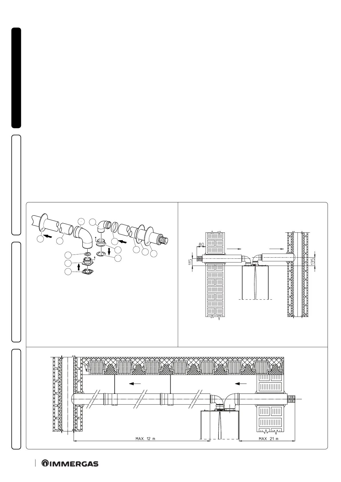
• Assembly of insulated separator kit Ø 80/80 (Fig. 23).
Install the ange (4) on the central hole of the boiler inserting
the gasket (1) and tighten using the hex head and at tip screws
contained in the kit, insert the anti-pulse plate up to the stop (5).
Remove the at ange contained in the side hole with respect
to the central one (as needed) and replace it with the ange
(3), positioning the gasket (2) already present in the boiler and
tighten using the supplied self-threading screws with tip. Insert
and slide cap (7) onto bend (6) from the male side (smooth), and
join bends (6) with the male side (smooth) in the female side
of ange (3). Fit bend (12) with the male side (smooth) into the
female side of ange (4). Fit the male end (smooth) of the intake
terminal (8) up to the stop on the female end of the bend (6),
making sure you have already inserted the wall sealing plates (9
and 10) that ensure correct installation between pipe and wall,
then x the closing cap (7) on the terminal (8). Join the exhaust
pipe (11) with the male side (smooth) in the female side of the
bend (12) to the end stop, ensuring that the wall sealing plate
(9) is already inserted for correct installation between the pipe
and ue.
• Insulation of separator terminal kit. Whenever there are ue
gas condensate problems in the exhaust pipes or on the external
surface of the intake pipes, on request Immergas supplies insu-
lated intake-exhaust pipes. Insulation my be necessary on the
exhaust pipe, due to excessive loss of temperature of the ue gas
on their route. Insulation may be necessary on the intake pipe as
the air entering (if very cold) may cause the outside of the pipe
to fall below the dew point of the environmental air. e gures
(Fig. 24-25) illustrate dierent applications of insulated pipes.
Insulated pipes are formed of a Ø 80 internal concentric pipe and
a Ø 125 external pipe with static air space. It is not technically
possible to start with both Ø 80 elbows insulated, as clearances
will not allow it. However starting with an insulated elbow is
possible by choosing either the intake or exhaust pipe. When
starting with the insulated intake bend it must be engaged on
its ange until it is taken up to end stop on the ue gas exhaust
ange, a situation that takes the two intake ue gas exhaust outlets
to the same height.
e kit includes:
N°1 - Exhaust gasket (1)
N°1 - Flange gasket (2)
N°1 - Female intake ange (3)
N°1 - Female exhaust ange (4)
N°1 - Anti-pulse plate (5)
N°1 - Bend 90° Ø 80 (6)
N°1 - Pipe closure cap (7)
N°1 - Intake terminal Ø 80
insulated (8)
N°2 - Internal wall sealing
plates (9)
N° 1 - External wall sealing
plate (10)
N°1 - Discharge pipe Ø 80
insulated (11)
N°1 - Concentric bend 90° Ø
80/125 (12)