47
4
TECHNICAL DATA.
4.1 VARIABLE HEAT OUTPUT.
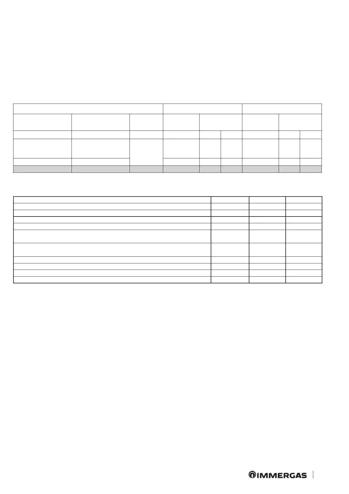
N.B.: the pressures indicated in the tables represent the dierence
in existing pressures between the gas valve outlet and the com-
bustion chamber. e adjustments should therefore,be carried
out using a dierential manometer (small "U"-shaped column
or digital manometer) with the probes inserted in the pressure
test gas valve outlet and on the sealed chamber positive pressure
test. e power data given in the table is obtained with 0.5m long
intake/exhaust pipe. Gas ow rates refer to heating power below a
temperature of 15°C and pressure of 1013 mbar. Burner pressure
values refer to use of gas at 15°C.
METHANE (G20) PROPANE (G31)
HEAT
INPUT
HEAT
OUTPUT
GAS FLOW
RATE BURNER
GAS PRESSURE
GAS FLOW
RATE BURNER
GAS PRESSURE
(kW) (kW) (kg/h) (kPa)
(%)
(kg/h) (kPa)
(%)
25.5 23.5
RISC
+
SANIT
2.70 1.14 100 1.04 3.62 100
12.8 11.3 1.35 0.31 19 0.52 0.94 18
7.6 6.7
SANIT
0.80 0.12 0 0.31 0.37 0
4.2 COMBUSTION PARAMETERS.
Combustion parameters: measuring conditions of useful eciency
(ow temperature/return temperature= 80 / 60 °C), ambient tem-
perature reference = 15°C.
G20 G31
Gas nozzle diameter mm 1.35 0.79
Supply pressure mbar (mm H
2
O) 20 (204) 37 (377)
Flue ow rate at nominal central heating output kg/h 53 54
Flue ow rate at min central heating output kg/h 55 57
CO
2
at Nom.
O
2
at Nom.
%
6.90
8.50
7.80
9.00
CO
2
at Min.
O
2
at Min.
%
3.20
15.20
3.50
15.60
CO with 0% O
2
at Nom./Min. Q. ppm 79 / 75 65 / 76
NO
X
with 0% O
2
at Nom./Min. Q. mg/kWh 215 / 151 279 / 187
Flue temperature at nominal output °C 128 133
Flue temperature at minimum output °C 108 110