7
8
14
INSTALLER
USER
MAINTENANCE TECHNICIAN
TECHNICAL DATA
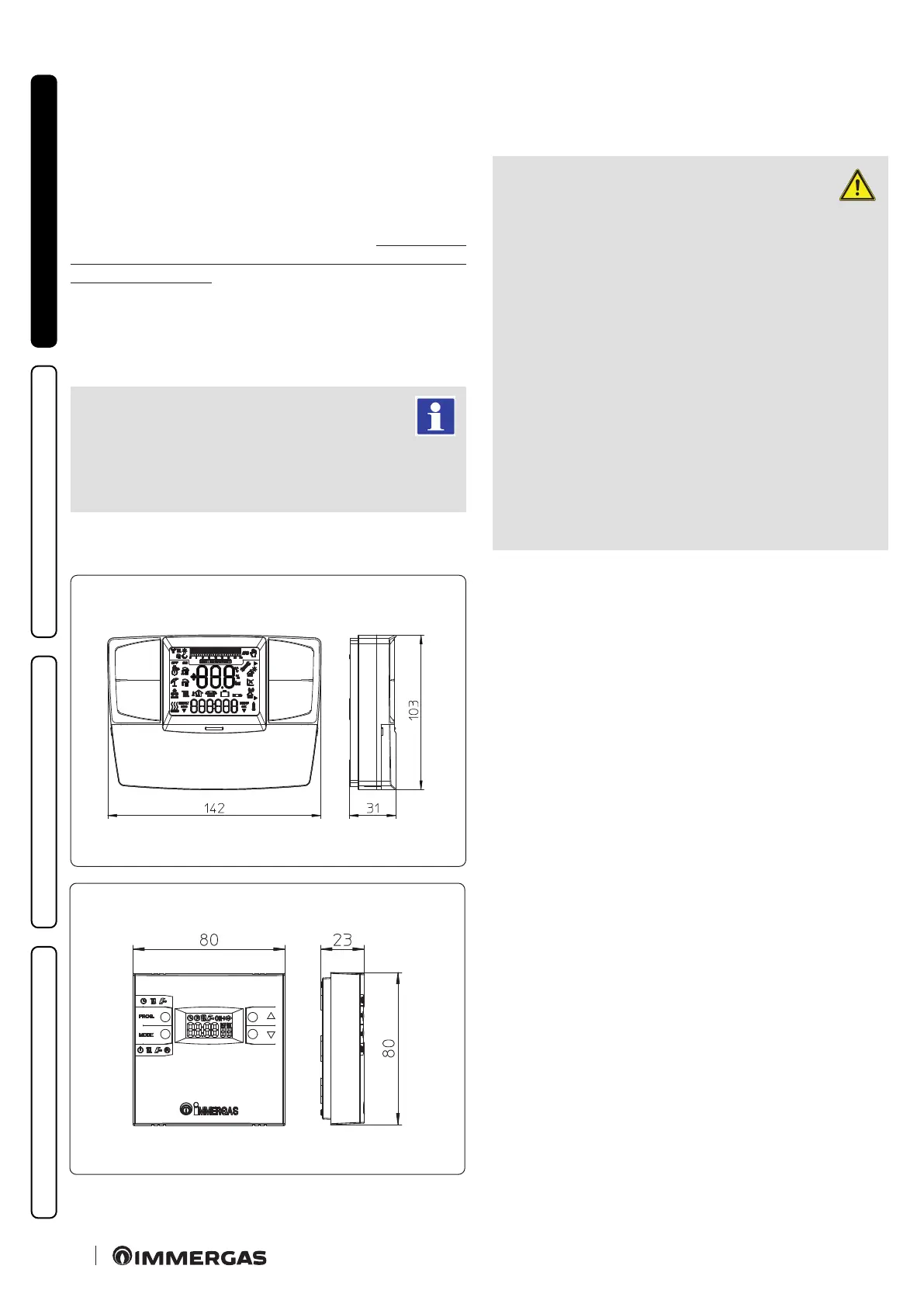
e climate regulator incorporated into the remote panels enables
the system ow temperature to be adjusted to the actual needs
of the room being heated, in order to obtain the desired room
temperature with extreme precision and therefore with evident
saving in running costs. e Mini CRD and CAR
V2
are fed di-
rectly by the boiler by means of the same 2 wires used for the
transmission of data between the boiler and devices.
Digital Remote Mini-Control or CAR
V2
or On/O chrono-
thermostat electrical connections (Optional). e operations
described below must be performed aer having removed the vol-
tage from the appliance. Any room chrono-thermostats or remote
controls must be connected to the 40 and 41 terminal blocks,
eliminating the X40 jumper (Fig. 36). Make sure that the On/O
thermostat contact is of the “clean” type, i.e. independent of the
mains voltage, otherwise the P.C.B. would be damaged. e boiler
can only be connected to one device at a time.
If the Mini CRD or CAR
V2
remote control is used,
arrange two separate lines in compliance with current
regulations regarding electrical systems. No boiler
pipes must ever be used to earth the electric system or
telephone lines. Ensure elimination of this risk before making
the boiler electrical connections.
1.9 IMMERGAS FLUE SYSTEMS.
Immergas supplies various solutions separately from the boilers
regarding the installation of air intake terminals and ue exhaust,
which are fundamental for boiler operation.
ATTENTION:
the boiler must be installed exclusively
with an original Immergas “Blue Ran-
ge” inspectionable air intake system and ue
gas extraction system made of plastic, with the
exception of the C6 conguration, as required
by the regulations in force and by the product’s
approval.
is ue can be identied by an identication
mark and special distinctive marking bearing
the note "only for condensation boilers".
e ue exhaust pipes must not be in contact
with or be near to ammable materials. Mo-
reover, they must not pass through buildings
or walls made of ammable material.
• Resistance factors and equivalent lengths.
Each ue component has a Resistance Factor based on exper-
imental tests and specied in the table below. e Resistance
Factor for individual components is independent from the type
of boiler on which it is installed and has a dimensionless size. It
is however, conditioned by the temperature of the uids that pass
through the pipe and therefore, varies according to applications
for air intake or ue exhaust. Each single component has a resist-
ance corresponding to a certain length in metres of pipe of the
same diameter; the so-called equivalent length, can be obtained
from the ratio between the relative Resistance Factors.
All boilers have an experimentally obtainable maximum Re-
sistance Factor equal to 100.
e maximum Resistance Factor allowed corresponds to the
resistance encountered with the maximum allowed pipe length
for each type of Terminal Kit. is information allows calcula-
tions to be made to verify the possibility of setting up various
ue congurations.
Note: to dimension the ue ducting using commercial compo-
nents, refer to the table of combustion parameters (Paragraph 4.2).