33
2
1
39
INSTALLER
USER
MAINTENANCE TECHNICIAN
TECHNICAL DATA
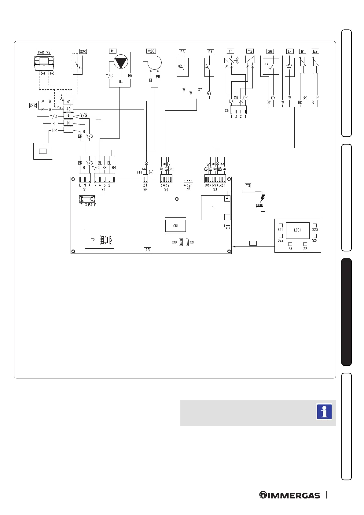
3.5 WIRING DIAGRAM.
Key:
A3 - Integrated P.C.B.
B1 - Flow probe
B2 - D.H.W. probe
CAR
V2
-
Comando Amico Remoto
V2
remote control (optional)
E3 - Ignition and detection electrode
E4 - Safety thermostat
F1 - Phase fuse
LCD1 - Display
M1 - Boiler pump
M20 - Fan
S2 - Selector switch functioning
S3 - Reset block key
S4 - D.H.W. ow switch
S5 - System pressure switch
S6 - Flue pressure switch
S20 - Room thermostat (optional)
S21 - Key to increase DHW
temperature
S22 - Key to decrease DHW
temperature
S23 - Key to increase central heating
temperature
S24 - Key to decrease central heating
temperature
T1 - Ignition transformer
T2 - Boiler P.C.B. transformer
X40 - Room thermostat jumper
Y1 - Gas valve
Y2 - Gas valve modulator
1 - User interface
2 - 230 Vac 50 Hz supply voltage
Comando Amico Remoto
V2
.
e boiler is set-up for the application of the Comando Amico
Remoto remote control V2 (CAR
V2
) or of the Mini CRD, which
must be connected to clamps 40 and 41, by observing polarity and
eliminating jumper X40.
Room thermostat.
e boiler is set-up for the application of the Room ermostat
(S20) which must be connected to clamps 40 and 41 and by eli-
minating jumper X40.
Colour code key:
BK - Black
BL - Blue
BR - Brown
G - Green
DY - Grey
OR - Orange
P - Purple
PK - Pink
R - Red
W - White
W/BK - White/Black
Y - Yellow
Y/G - Yellow/Green
e X5 connector is used for automatic inspection.
e user interface is on the welding side of the boiler
board