C
52
26
24
INSTALLER
USER
MAINTENANCE TECHNICIAN
TECHNICAL DATA
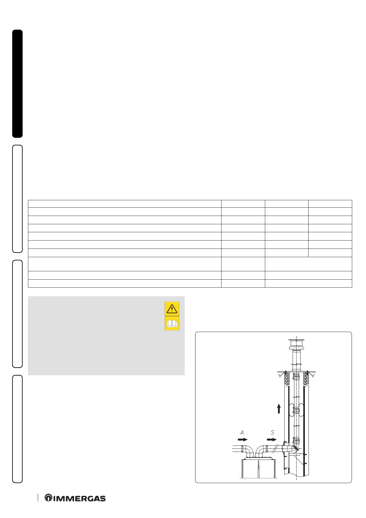
1.14 DUCTING OF FLUES OR TECHNICAL SLOTS.
Ducting is an operation through which, via the introduction of
one or more relevant pipes, one achieves a system for the evacua-
tion of the combustion products of a gas appliance, made up from
the coupling of an existing or new ducting pipe with a chimney,
ue or technical slot (also in new buildings) (Fig. 26).
Ducting requires ducts declared to be suitable for the purpose by
the manufacturer, following the installation and user instruc-
tions, provided by the manufacturer and the requirements of the
regulations in force.
In any case, ducting operations must respect the provisions con-
tained in the standard and in current technical regulations;
e instructions in the project or technical report must likewise
be followed, in cases provided for by the standard and current
technical regulations.
To guarantee reliability and operation over time of the ducting
system, make sure:
- it is used in average atmospheric and environmental conditions,
according to current regulations (absence of combustion pro-
ducts, dusts or gases that can alter the normal thermophysical or
chemical conditions; existence of temperatures coming within
the standard range of daily variation, etc.).
- Installation and maintenance must be performed according to
the indications supplied by the manufacturer included with the
“blue range” ducting system chosen and in compliance with the
regulations in force.
- e maximum length specied by the manufacturer must be
respected; in this regard:
• e max. possible length of the Ø80 exible ducting vertical
section is equal to 6.7m. is length is obtained considering the
Ø80 complete exhaust terminal, 1m of Ø80 pipe in exhaust,
two 90° Ø80 bends at boiler outlet for connecting to the ducting
system and two direction changes of the exible hose inside the
chimney/technical slot.
• e max. possible length of the Ø80 exible ducting vertical
section is equal to 27m. is length is obtained considering the
complete Ø80 exhaust terminal, 1m of Ø80 pipe in exhaust,
two 90° Ø80 bends at boiler outlet.
1.15 CONFIGURATION FOR C6 FLUE INSTALLATION.
Appliance designed to be connected to a commercial exhaust/
intake system.
Gas type G20 G31
Flue temperature at maximum output °C 128 133
Flue gas mass at maximum power kg/h 53
54
Flue temperature at minimum output °C 108 110
Flue gas mass at minimum power kg/h 55 57
CO
2
at Q. max. % 6,9 7,8
CO
2
a Q. minimum % 3,2 3,5
Maximum head available at the ue at maximum power
(maximum resistance value of the commercial ue system)
Pa 89
Maximum head available at the ue at minimum power
Pa 89
Maximum temperature achievable in the exhaust ducts
°C 180
- Ducts must withstand condensation (only for con-
densing models);
- Air intake ducts must withstand working air tem-
peratures of up to 60°C;
- e maximum permissible percentage of ue gas
recirculation in windy conditions is 10%.
- Suction and exhaust pipes cannot be installed on opposing
walls;
- With ues in conguration C
6
discharge into pressurised
ues is not permitted.