5
4
3
1
2
1
2
3
4
5
6
C13
C13
C13
C13
10 - IE
INSTALLERUSER
MAINTENANCE TECHNICIAN
Fig. 1-13 Fig. 1-14
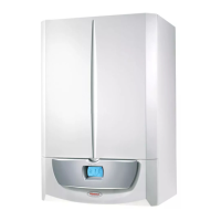
e kit includes:
N° 1 - Gasket (1)
N° 1 - Concentric bend Ø60/100 (2)
N° 1 - Concentric intake-exhaust terminal Ø60/100 (3)
N° 1 - Internal white wall sealing plate (4)
N° 1 - External grey wall sealing plate (5)
Fig. 1-15
Fig. 1-16
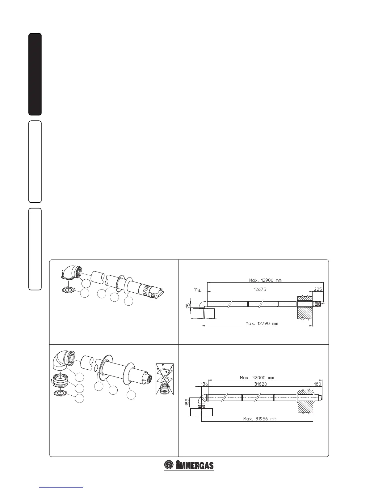
e adapter Kit includes:
N° 1 - Gasket (1)
N° 1 - Adapter
Ø80/125 (2)
1.10 HORIZONTAL CONCENTRIC KIT
INSTALLATION.
Type C configuration, sealed chamber and
fan assisted.
Horizontal intake - exhaust kit Ø60/100. Kit
assembly (Fig. 1-13): install the bend with ange
(2) on the central hole of the boiler, positioning
the gasket (1) (which does not require lubrication)
positioning it with the circular projections
downwards in contact with the boiler ange
and tighten using the screws preset in the kit.
Fit the Ø60/100 (3) concentric terminal pipe
with the male end (smooth) to the female end
of the bend (2) up to the stop; making sure that
the internal and external wall sealing plate have
been tted, this will ensure sealing and joining
of the elements making up the kit.
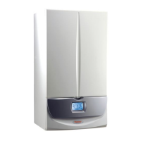
• Extensions for horizontal kit Ø60/100
(Fig. 1-14). e kit with this conguration
can be extended up to a max. horizontal
distance of 12.9 m including the terminal with
grid and excluding the concentric bend leaving
the boiler. is conguration corresponds to
a resistance factor of 100. In these cases the
special extensions must be requested.
Horizontal intake - exhaust kit Ø80/125. Kit
assembly (Fig. 1-15): for the installation of kit
Ø80/125 the anged adapter kit must be used to
be able to install the ue system Ø80/125. Install
the anged adapter (2) on the central hole of the
boiler, positioning the gasket (1) (which does not
require lubrication) with the circular projections
downwards in contact with the boiler ange and
tighten using the screws present in the kit. Engage
the bend (3) with the male side (smooth) until it
is fully home on the adapter (1). Fit the Ø80/125
(5) concentric terminal pipe with the male end
(smooth) to the female end of the bend (4)
(with lip seal) up to the stop; making sure that
the internal (6) and external wall sealing plates
(7) have been tted, this will ensure sealing and
joining of the elements making up the kit.
• Extensions for horizontal kit Ø80/125
(Fig. 1-16). e kit with this conguration
can be extended up to a max. distance of 32 m
including the terminal with grid and excluding
the concentric bend leaving the boiler. If
additional components are assembled, the
length equivalent to the maximum allowed
must be subtracted. In this case the special
extensions must be requested.
• External grid. N.B.: for correct functioning
of the system the terminal with grid must be
installed correctly ensuring that, the "high"
indication present on the terminal is respected
on installation.
e Kit Ø80/125 includes:
N° 1 - Concentric bend Ø80/125 at
87° (3)
N° 1 - Concentric intake-exhaust
terminal Ø80/125 (4)
N° 1 - Internal wall sealing plate (5)
N° 1 - External wall sealing plate (6)
e remaining components of the kit are
not to be used