31 - IE
INSTALLERUSER
MAINTENANCE TECHNICIAN
3.9 "CHIMNEY SWEEP FUNCTION" F2.
If this function is activated it takes boiler
functioning to the adjustable power of the central
heating selector switch.
In this state all adjustments are excluded and only
the safety thermostat and the limit thermostat
remain active. To activate the chimney sweep
press the Reset button "C" for a time between 8
and 15 seconds in absence of domestic hot water
and heating requests. Its activation is signalled by
the relative symbol (22 Fig. 2-1). is function
allows the technician to check the combustion
parameters. After the checks deactivate the
function, switching the boiler o and then on
again using the Stand-by button.
3.10 PUMP ANTIBLOCK FUNCTION.
e boiler has a function that starts the pump at
least once every 24 hours for the duration of 30
seconds in order to reduce the risk of the pump
becoming blocked due to prolonged inactivity.
3.11 THREEWAY ANTIBLOCK
FUNCTION.
Both in “domestic hot water” and in “domestic
hot water-central heating” phase the boiler is
equipped with a function that starts the three-
way motorised group 24 hours aer it was last
in operation, running it for a full cycle so as to
reduce the risk of the three-way group becoming
blocked due to prolonged inactivity.
3.12 RADIATORS ANTIFREEZE
FUNCTION.
If the system return water temperature is near
to freezing, the boiler starts up until reaching a
safe temperature.
3.13 P.C.B. PERIODICAL SELFCHECK.
During functioning in heating mode or with
boiler in standby, the function activates every 18
hours aer the last boiler check/power supply. In
case of functioning in domestic hot water mode
the self-check starts within 10 minutes aer the
end of the withdrawing in progress, for duration
of approx. 10 seconds.
N.B.: during self-check, the boiler remains o.
3.14 AUTOMATIC VENT FUNCTION.
In the case of new heating systems and in
particular mode for floor systems, it is very
important that dearation is performed correctly.
To activate the “F8” function, press buttons “A
and B” at the same time (Fig. 2-1) for 5 seconds
with boiler in stand-by. e function consists in
the cyclic activation of the pump (100 s ON, 20
s OFF) and the 3-way valve (120 s domestic hot
water, 120 s central heating). e function ends
aer 18 hours or by switching the boiler on using
the ignition button “
”.
3.15 SOLAR PANELS COUPLING
FUNCTION.
e boiler is set-up to receive pre-heated water
from a system of solar panels up to a maximum
temperature of 65 °C. In the case of use with
higher temperatures it is recommended to install
a mixing valve on the hydraulic circuit upstream
from the boiler. Set the “P 71” function on “P
71.1” (Par. 3.8).
When the boiler inlet water is at a temperature
that is equal or greater with respect to that set by
the domestic hot water selector switch “SET”, the
boiler does not switch on.
3.16 YEARLY CONTROL AND
MAINTENANCE OF THE
APPLIANCE.
e following checks and maintenance should
be performed at least once a year.
- Clean the ue side of the heat exchanger.
- Clean the main burner.
- Check correct ignition and functioning.
- Ensure correct calibration of the burner in
domestic water and heating phases.
- Check correct functioning of appliance control
and adjustment devices and in particular:
- the intervention of main electrical switch on
the boiler;
- system control thermostat intervention;
- domestic hot water control thermostat
intervention.
- Check sealing eciency of gas circuit and the
internal system.
- Check intervention of the device against no gas
ionization ame control:
- check that the relative intervention time is
less than 10 seconds.
- Visually check for water leaks or oxidation
from/on connections and traces of condensate
residues inside the sealed chamber.
- Check, by means of the condensate drain cap,
that there are no residues of material blocking
the ow of condensate.
- Check contents of the condensate drain trap.
- Visually check that the water safety drain valve
is not blocked.
- Check that, aer discharging system pressure
and bringing it to zero (read on boiler
manometer), the expansion vessel charge is at
1.0 bar.
- Check that the system static pressure (with
system cold and aer relling the system by
means of the ller cock) is between 1 and 1.2
bar.
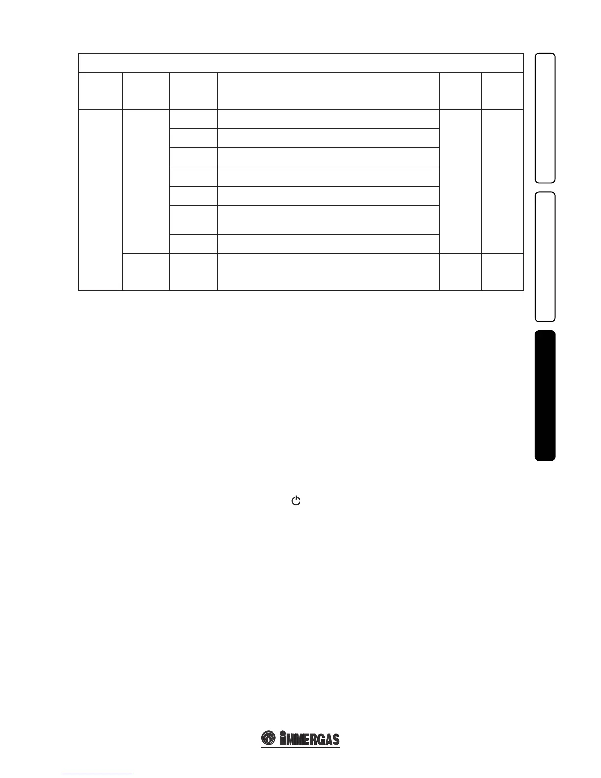
M5 menu
(password must be entered)
1
st
Level 2
nd
Level Options Description
Default
value
Value
set
by the
technician
RELE3
(optional)
RELE3-0 Relay 3 not used.
RELE3-0
RELE3-1
Check the storage tank recirculation pump.
(not usable on this model).
RELE3-2
e relay signals the intervention of boiler block ( Can be coupled to an
external signalling device, not supplied).
RELE3-3
e relay signals that the boiler is on in heating phase.
(Can be coupled with an external pump, not supplied).
RELE3-4
Controls the opening of an external gas valve in concomitance with an
ignition request of the boiler burner.
RELE3-5
Operation with heat pump. Coupled to the 2-5 operation of relay 2 and
an interface (not supplied) allows the management of the boiler coupled
to a heat pump.
RELE3-6
In case the boiler pump needs to be replaced with a traditional pump at
xed speed it is necessary to connect the new pump to the relay board.
P76
-15°C ÷
+14°C
CE
With S34 = On. If the reading of the external probe is not correct it is possible
to correct it in order to compensate any environmental factors.
With S34 = O and system supervisor connected, set the parameter to
maximum until the CE value appears.
0°C