+
+
3
12
2
1
P1
P3
+
+
3
12
1
P1
2
P3
27 - IE
INSTALLERUSER
MAINTENANCE TECHNICIAN
3.4 CONVERTING THE BOILER TO
OTHER TYPES OF GAS.
If the boiler has to be converted to a dierent gas
type to that specied on the data plate, request
the relative conversion kit for quick and easy
conversion.
Boiler conversion must be carried out by a
qualied technician (e.g. Immergas Aer-Sales
Technical Assistance Service).
To convert to another type of gas the following
operations are required:
- remove the voltage from the appliance;
- replace the nozzle located between the gas pipe
and gas/air mixing sleeve (Part. 6 Fig. 1-29),
taking care to remove the voltage from the
appliance during this operation;
- apply voltage to the appliance;
- calibrate the number of fan revs. (Par. 3.5);
- adjust the correct air/gas ratio (Par. 3.6);
- seal the gas ow rate devices (if adjusted);
- aer completing conversion, apply the sticker,
present in the conversion kit, near the data-
plate. Using an indelible marker pen, cancel
the data relative to the old type of gas.
ese adjustments must be made with reference
to the type of gas used, following that given in
the table (Par. 3.18).
3.5 CALIBRATION OF NUMBER OF FAN
REVS.
Attention: verification and calibration is
necessary, in the case of transformation to other
types of gas, in the extraordinary maintenance
phase with replacement of the circuit board,
air/gas circuit components or in the case of
installations with fume extraction systems, with
horizontal concentric pipe measuring more
than 1 metre.
The boiler heat output is correlated to the
length of the air intake and ue exhaust pipes.
is decreases with the increase of pipe length.
The boiler leaves the factory adjusted for
minimum pipe length (1m). It is therefore
necessary, especially in the case of maximum
pipe extension, to check the ∆p gas values aer at
least 5 minutes of burner functioning at nominal
heat output, when the temperatures of the intake
air and exhaust ue gases have stabilised. Adjust
the nominal and minimum heat output in the
domestic hot water and central heating modes
according to the values in the table (Par. 3.18)
using the dierential manometers connected to
the ∆p gas pressure point (13 and 14 Fig. 1-29).
Enter in the M5 menu (Parag. 3.8) and adjust
the ignition power “P50”, meanwhile under
“SERVICE” adjust the following parameters:
- boiler maximum heat output “P62”;
- boiler minimum heat output “P63”;
- maximum central heating output “P64”;
- minimum central heating output “P65”.
Below nd the default settings present on the
boiler:
P50 36 % 40%
P62
G20:
5100 (rpm)
LPG:
4600 (rpm)
P63
G20:
980 (rpm)
LPG:
1020 (rpm)
P64
G20:
5100 (rpm)
LPG:
4600 (rpm)
P65
G20:
980 (rpm)
LPG:
1020 (rpm)
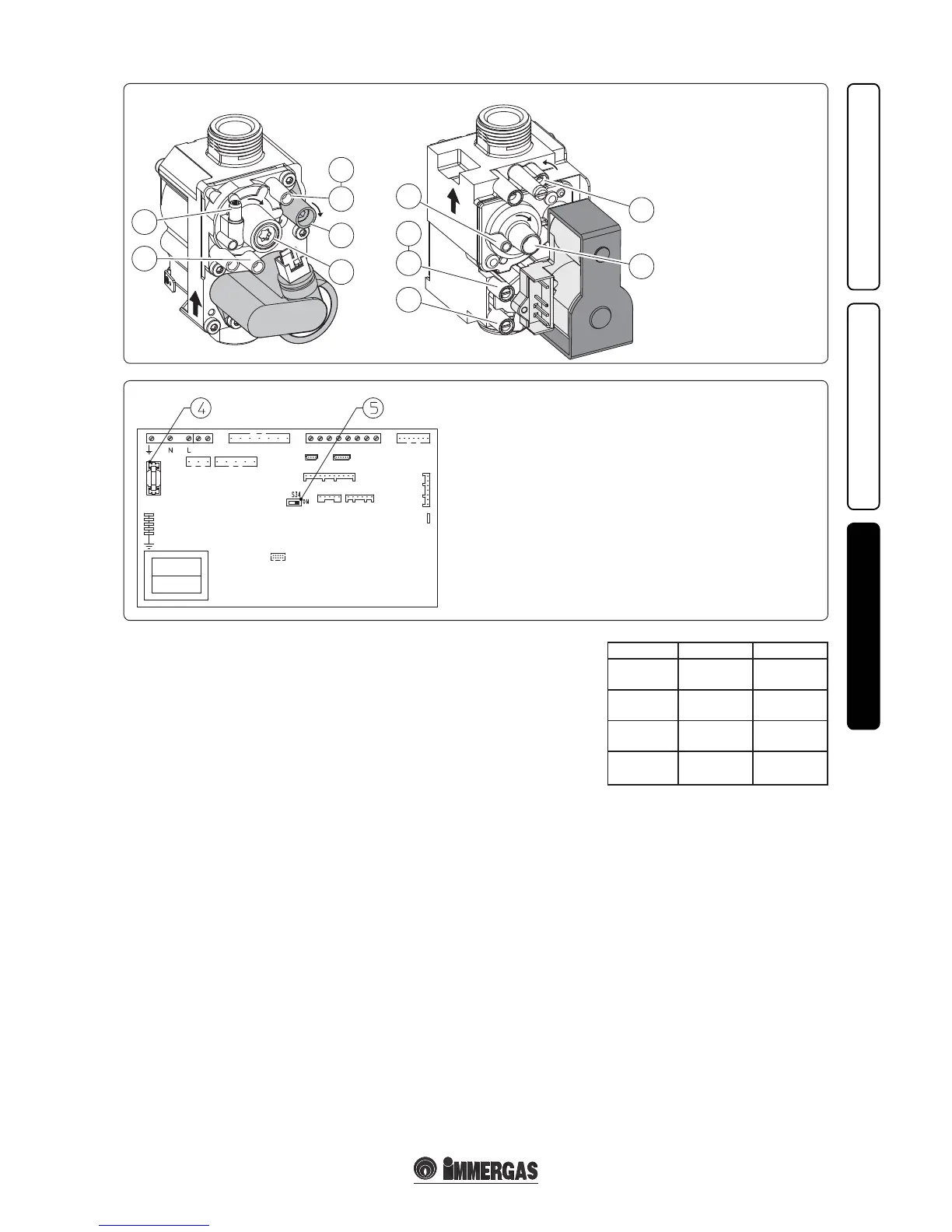
P.C.B.
Fig. 3-3
Fig. 3-4
Key:
1 - Gas valve inlet pressure
point
2 - Gas valve outlet pressure
point
3 - O/Set adjustment screw
12 - Outlet gas ow rate
adjuster
Gas Valve 8205 Gas Valve 848
Key:
4 - 3,15 AF fuse
5 - S34 selector: On = external probe; O = system supervisor