C33
C33
C33
C33
7
4
6
5
1
2
3
1
2
3
4
5
6
7
11 - IE
INSTALLERUSER
MAINTENANCE TECHNICIAN
Fig. 1-18
Fig. 1-20Fig. 1-19
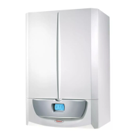
e kit includes:
N° 1 - Gasket (1)
N° 1 - Female concentric ange (2)
N° 1 - Wall sealing plate (3)
N° 1 - Aluminium tile (4)
N° 1 - Int./exhaust concentric pipe
Ø60/100 (5)
N° 1 - Fixed half-shell (6)
N° 1 - Mobile half-shell (7)
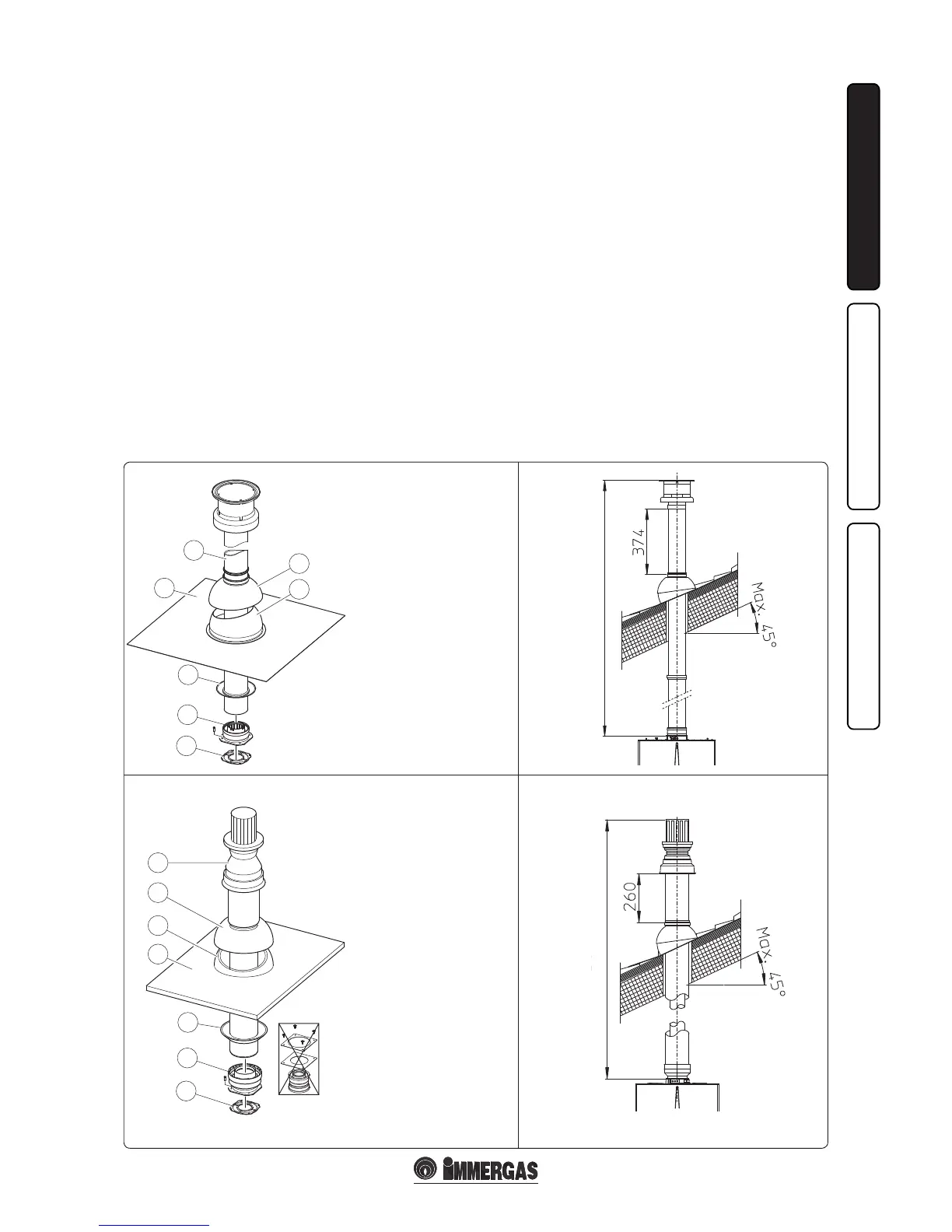
e adapter Kit includes:
N° 1 - Gasket (1)
N° 1 - Adapter
Ø80/125 (2)
e Kit Ø80/125 includes:
N° 1 - Wall sealing plate (3)
N° 1 - Aluminium tile (4)
N° 1 - Fixed half-shell (5)
N° 1 - Mobile half-shell (6)
N° 1 - Int./exhaust concentric
pipe Ø80/125 (7)
e remaining components of the
kit are not to be used
1.11 VERTICAL CONCENTRIC KIT
INSTALLATION.
Type C configuration, sealed chamber and
fan assisted.
Vertical concentric of intake and exhaust kit.
is terminal enables the air intake and the ue
exhausts to be directly emitted outside the house
in a vertical direction.
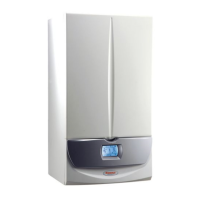
N.B.: the vertical kit with aluminium tile
enables installation on terraces and roofs with
a maximum slope of 45% (approximately 25°)
and the height between the terminal cap and
half-shell (374 mm for Ø60/100 and 260 mm for
Ø80/125) must always be respected.
Vertical kit with aluminium tile Ø60/100.
Kit assembly (Fig. 1-17): install the concentric
flange (2) on the central hole of the boiler,
positioning the gasket (1) (which does not
require lubrication) with the circular projections
downwards in contact with the boiler ange and
tighten using the screws present in the kit.
Imitation aluminium tile installation: replace the
tile with the aluminium sheet (4), shaping it to
ensure that rainwater runs o. Position the xed
half-shell (6) and insert the intake-exhaust pipe
(5). Fit the Ø60/100 (3) concentric terminal pipe
with the male end (5) (smooth) into the ange (2)
up to the stop; making sure that the wall sealing
plate has been tted (3), this will ensure sealing
and joining of the elements making up the kit.
• Extensions for vertical kit Ø60/100 (Fig. 1-18).
The vertical kit with this configuration
can be extended to a max. straight vertical
length of 14.4 m including the terminal. is
conguration corresponds to a resistance factor
of 100. In this case the special extensions must
be requested.
Vertical kit with aluminium tile Ø80/125.
Kit assembly (Fig. 1-19): for the installation of kit
Ø80/125 the anged adapter kit must be used to
be able to install the ue system Ø80/125. Install
the anged adapter (2) on the central hole of the
boiler, positioning the gasket (1) (which does not
require lubrication) with the circular projections
downwards in contact with the boiler ange
and tighten using the screws preset in the kit.
Imitation aluminium tile installation: replace
the tile with the aluminium sheet (4), shaping
it to ensure that rainwater runs o. Position
the xed half-shell (5) on the aluminium tile
and insert the intake-exhaust pipe (7). Fit the
Ø80/125 concentric terminal pipe with the male
end (smooth) to the female end of the adapter
(1) (with lip gasket) up to the stop; making sure
that the wall sealing plate has been tted (3), this
will ensure sealing and joining of the elements
making up the kit.
• Extensions for vertical kit Ø80/125 (Fig. 1-20).
e vertical kit with this conguration can be
extended to a max. length of 32 m including
the terminal. If additional components are
assembled, the length equivalent to the
maximum allowed must be subtracted. In this
case specic extensions must be requested.
Fig. 1-17
MAX. LENGTH 14400 MM
MAX. LENGTH 32000 MM