30 - IE
INSTALLERUSER
MAINTENANCE TECHNICIAN
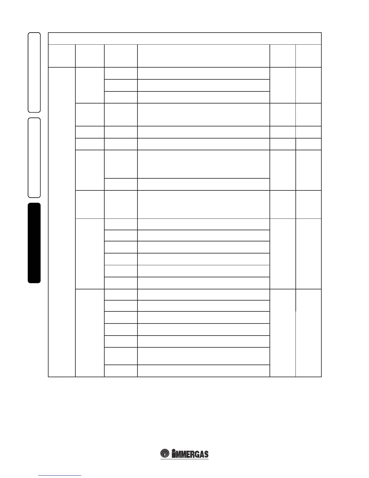
M5 menu
(password must be entered)
1
st
Level 2
nd
Level Options Description
Default
value
Value
set
by the
technician
SERVICE
P67
P67.1
In winter mode the pump is always powered and so functions
continuously.
P67.2P67.2
In winter mode the pump is managed by the room thermostat or by the
remote control.
P67.3
In winter mode the pump is managed by the room thermostat or by the
remote control and by the boiler ow probe.
P68 0s ÷ 500s
e boiler is set to ignite the burner immediately aer a request for
heating. In the case of particular systems (e.g. area systems with
motorised thermostatic valves etc.) it could be necessary to delay
switch-on.
0 seconds
P69 0s ÷ 255s
e boiler has an electronic timing device that prevents the burner
from igniting too oen in the central heating phase.
180 seconds
P70 0s ÷ 840s
e boiler performs an ignition ramp to arrive from minimum power
to nominal heat output.
180 seconds
(3 minutes)
P71
P71.1
OFF domestic hot water “correlated” to the switch-o of the boiler
takes place on the basis of the temperature set using the domestic hot
water adjustment selector switch. Solar function active, if the input
domestic hot water has a sucient temperature the boiler does not
switch on.
P71.2
P71.2
xed domestic hot water OFF; the boiler switches o at 65°C.
Solar function deactivated.
P72
AUTO
OFF
09 L/M
12 L/M
15 L/M
e boiler allows to set the ow rate adjuster on the various levels.
Auto (automatic functioning, therefore with variable ow rate).
Open (adjuster completely open therefore maximum ow rate
available).
08 L/M, 10 L/M and 12 L/M (unctioning with dened ow rate).
AUTO
RELE1
(optional)
RELE1-0 Relay 1 not used.
RELE1-1
RELE1-1 In a system divided into zones, relay 1 controls the main zone.
RELE1-2
e relay signals the intervention of boiler block ( Can be coupled to
an external signalling device, not supplied).
RELE1-3
e relay signals that the boiler is on in heating phase.
(Can be coupled with an external pump, not supplied).
RELE1-4
Controls the opening of an external gas valve in concomitance with an
ignition request of the boiler burner.
RELE1-5
In case the boiler pump needs to be replaced with a traditional pump at
xed speed it is necessary to connect the new pump to the relay board.
RELE2
(optional)
RELE2-0 Relay 2 not used.
RELE2-0
RELE2-1 In a system divided into zones, relay 2 controls the secondary zone.
RELE2-2
e relay signals the intervention of boiler block ( Can be coupled to
an external signalling device, not supplied).
RELE2-3
e relay signals that the boiler is on in heating phase.
(Can be coupled with an external pump, not supplied).
RELE2-4
Controls the opening of an external gas valve in concomitance with an
ignition request of the boiler burner.
RELE2-5
Operation with heat pump. Coupled to the 3-5 operation of relay 3
and an interface (not supplied) allows the management of the boiler
coupled to a heat pump.
RELE2-6
In case the boiler pump needs to be replaced with a traditional pump at
xed speed it is necessary to connect the new pump to the relay board.