IDS440 Users Manual version 4.2
66
ANALOG OUTPUT OPTION
ANALOG OUTPUT OPTION
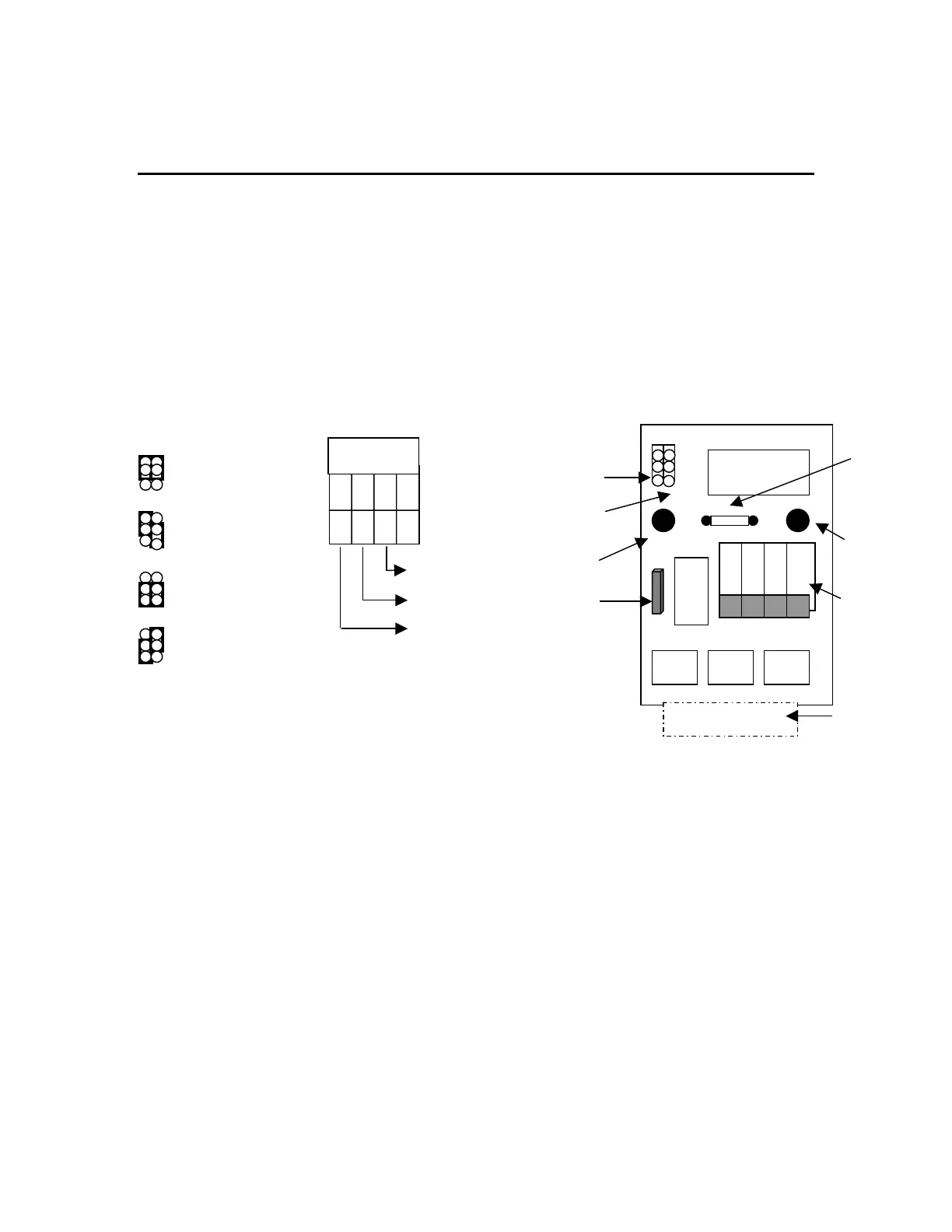
The Analog Output option board is internally mounted inside the indicator. The Analog
Output has two jumpers; JP1 & JP2. These jumpers are used to configure the output
format. Terminal block TB1 is for making external wiring connections. JP1 & JP2 are
factory set for 4-20mA. Refer to the diagram below for configuration, format and
alternative wiring. No interconnect cables are provided by the factory, the recommended
cables used should be suitable for the conduit fittings and should comply with National
Electrical code requirements.
INSTALLATION OF ANALOG OUTPUT BOARD
1. Before installation, remove power from the indicator and remove the back plate to
access the internal board.
2. Install the (2) plastic standoffs into the holes on the CPU board and plug the
analog output board (J1) onto the analog output connector marked J2 on the CPU
board. Secure the analog output module to the CPU board by pushing the
standoffs through the holes on the module.
3. Set JP1 and JP2 according to the desired output and connect the external device to
TB1 according to the selected output.
4. Apply power to the indicator and configure parameters 81, 82, and 83 as
described in the table below.
Analog
Output
Standoff
1 2 3 4
Ground
Voltage
Current
TB1
0- 5 VDC output
JP2/1
4-20 ma output
0-24mA output
0-20mA output
0-10 VDC option
U3
1 2 3 4
U U U
J1 16 pin header
JP1
JP2
TB1
U2
1
Standoff
hole
10 VDC output
R4 o
tion
R4
Optional
500ohm
0-10VDC
R4