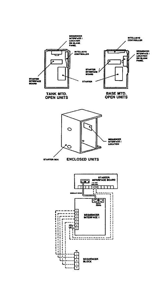
FIGURE 1
INTERFACE MOUNTING LOCATION
FIGURE 2 - WIRING DIAGRAM
SEQUENCE CONTROLLER INSTRUCTIONS
FOR MODELS:
SSR 10-450 HORSEPOWER
TWO, THREE, FOUR OR FIVE UNIT COMPRESSOR INSTALLATIONS
When two or more compressors, each designed for automatic start-up control,
operate together one should always be the “lead” unit. If this “lead” compressor
can maintain the required plant air pressure, all other compressors should be set
to shut down. This can be done by setting all compressor off line values at
different settings. The obvious result of doing this is that the compressors do not
log equal operating hours-the compressor with the pressure switch set at the
highest pressure level will log far more hours than the other compressors.
To make any compressor a lead machine and, on a rotative basis, equalize the
operating hours for each of the compressors, a sequence controller is used. By
interconnecting a rotary drum switch and a group of auxiliary pressure
switches(one for each compressor), it is possible to revise the order of automatic
operation of the compressors without making individual adjustments to the
compressors. Each pressure switch in the sequence controller senses line
pressure, (introduced via a manifolded tubing assembly), and controls the
compressor to which it has been connected electrically.
A three compressor installation in a plant which has a minimum pressure
requirement of 90 psig could have its sequence controller pressure switches set
as follows-using varying pressure differential settings.
After time delay, each compressor will shut down at or above its “switch opening
pressure” and will automatically re-start at the “reset pressure”. From the setting
shown, step rotation of the sequence selector switch connects the pressure
switch 1 to the control leads of compressor No. 2, making it the lead machine-
and pressure switch II to compressor No. 3 making it the No. 1 lag compressor.
Compressor No. 1 which was the lead machine would become the No. 2 lag unit.
One more step of switch rotation continues the progression, so that each
compressor, in turn, becomes the lead unit.
A pointer, on the sequence panel face, indicates which unit is in the lead position.
Local-sequence selector switches, one for each compressor are mounted on
the sequence controller. These switches enable an operator to put any
compressor in sequence control or local control.
An indicating light, mounted above each selector switch, is lit when its corre-
sponding compressor is placed in sequence control.
When a compressor is in local control, it will operate in the automatic start-stop
mode but under the control of its own pressure switch (1PS).
SWITCH OPENING RESET
COMPRESSOR PRESSURE POSITION PRESSURE (PSIG) PRESSURE (PSIG)
1 I LEAD 100 94
2 II 1 LAG 98 92
3 III 2 LAG 95 90
-33-
-34-
 Loading...