Chapter 2 Wiring
2.1 Connection Mode
U
V
˳
PGcard
˄MD38PG4˅
CNR1
External keyboard
interface
OP
+24V
DI1
DI2
DI3
DI4
DI5
COM
AI1
AI2
GND
Pressure command:0~10V
Flow command:0~10V
+13V
AI3
GND
Pressure sensor signal
GND
V+
OUTPUT
PTC-P-1
PTC-N-1
Thermistor ˄PTC×××˅
CANH CGND
CANL
485B 485A
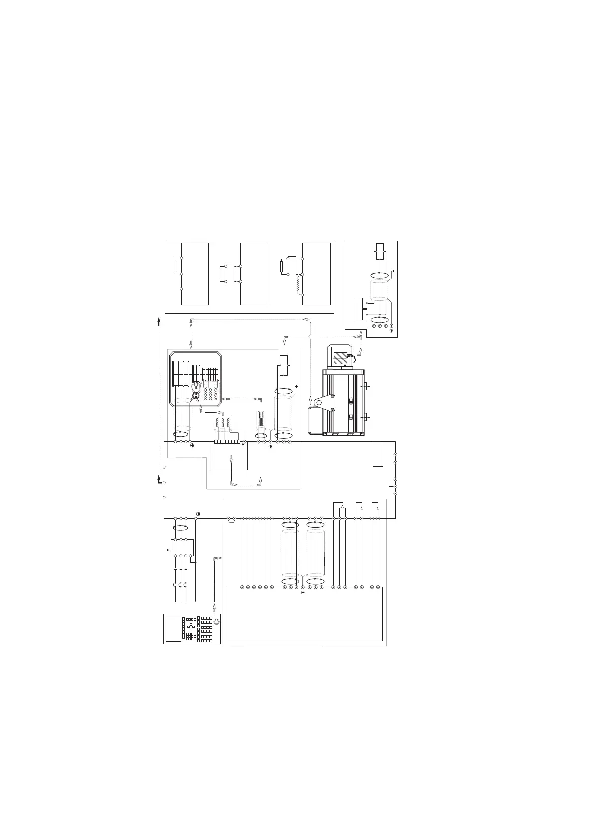
Oil pump
enabled
PID selection terminal 1
PID Selection terminal 2
Fault reset
CAN Communication Enabled ( use when
Multi-pump parallel flow)
Motor overheating
protection terminal
0~10V/0~20mA
Actual pressure
output:0~10V/0~20mA
EXC
/EXC
SIN
SINLO
COS
PTC-P-2 (Reserved)
PTC-N-2 (Reserved)
COSLO
PTC-P
PTC-N
PTC-P
PTC-N
U
V
W
L1
L2
L3
EXC
/EXC
SIN
SINLO
COS
COSLO
Red&white
Yellow&white
yellow
blue
red
black
TS2640N321E64
The colored line
correspo nds to Tama
rotary t ransfor mer.
Model:
TS2640N321F64
Please connect
thermistor
devices. Thermal
galvanic devices
connect to the
resistance- ruler
location of the
system co mputer .
Toroidal Core (around one circle)
Shielded
network
Shielded Network
(Connector metal shell)
Generally, the motor
thermist or connects to
PTC-P-1 and PTC-N-1.
System Computer
GND
Ferrite Bead(In the same
direction around two circles)
Ferrite Bead(In the same
direction around two circles)
Ferrite Bead (In the same
direction around two circles)
0~10V/0~20mA
Actual flow output:0~10V/0~20mA
GND
Ferrite Bead(In the same direction
around two circles)
AO1
AO2
GND
T/A1
T/B1
T/C1
T/A2
T/C2
T/A3
T/C3
˄RELAY1:Fault output˅
˄RELAY2˖Swash plate switching of
double displacement plunger pump˅
˄RELAY3˖
Pressure control status
output
˅
1
2
3
4
5
6
7
8
9
SENSOR
R
S
T
R
S
T
ilter
Contactor MC
Circuit Breaker
MCCB
Toroidal Core
(around on e circle)
L1
L2
L3
P
E
L1
L2
L3
P
E
Shielded
network
Shielded network
Brake Circuit
Connection
˄-˅˄+˅
PB
Brake Resistor
IS300T005IS300T050
˄-˅˄+˅
Brake Resistor
MDBU
IS300T070IS300T100
˄+˅˄-˅
Brake Resistor
MDBU
P
External
Reactor
IS300T140IS300T300
Schematic Diagram
for Connection of
Main Circuit and
Control Terminals
Break Circuit Connections
Shielded twisted-pair
cabling
Shielded twisted-
pair cabling
+13V
AI3
GND
GND
V+
OUTPUT
SENSOR
Shielded
network
Power Supply
GND 24V
Adopt the connection mode of the external power supply
pressure sensor (recommened)
Ferrite Bead(In the same direction
around two circles)
Ferrite Bead (In the same
direction around two circles)
Ferrite Bead(In the same direction
around two circles)
Ferrite Bead(In the same
direction around two circles)
Ferrite Bead(In the same
direction around the two circles)
Shielded
network
Hang in the air
efesotomasyon.com

 Loading...

