- 136 -
•
Multi-pump mode 2 (A2-03 = 1)
The following table lists the parameter setting of the slave drive. Perform the same parameter setting as you
do in the common servo pump mode.
Function Code Parameter Name Setting Description
A2-01 CAN communication address > 1 Slave drive
F4-** Slave pump address selection terminal 1 53 When the slave pump is used as the master
pump, it need be triggered by the terminal. For
the slave pump address setting, refer to section
B.3 Parameter Setting on Master Drive.
F4-** Slave pump address selection terminal 2 54
B.5 Applications of Multi-pump Convergent and Distributed Flow Control
B.5.1 Multi-pump Mode 1 (A2-03 = 0)
For example, the IMM servo pump system consists of three pumps with the address set as 1#, 2# and 3#. In the
multi-pump mode 1, when a slave pump is used as the master pump, the slave pump does not follow its speed.
There are the follwoing two combinations:
•
Combination 1: 3-pump convergent ow
•
Combination 2: 2+1 combination for distributed ow control, the 1# master pump is followed by the 2# slave
pump, and the 3# pump switches over to the master pump.
■
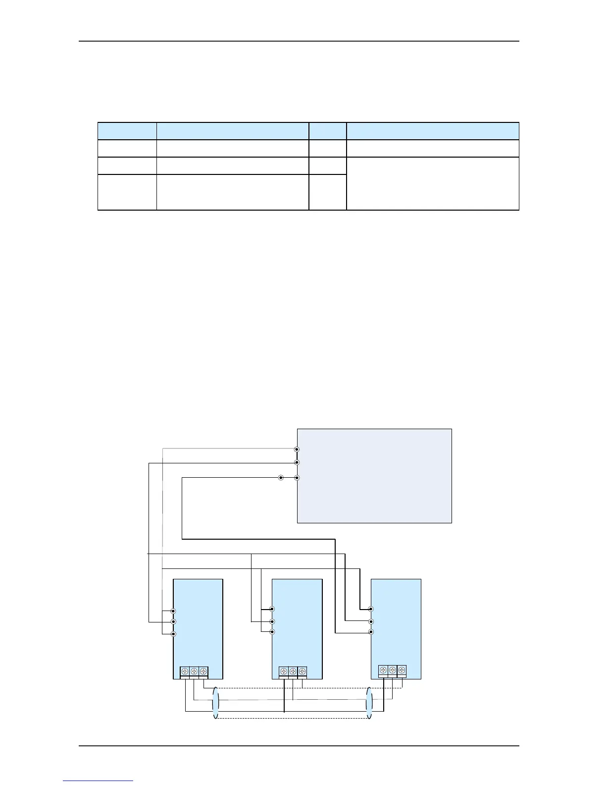
Combination 1: 3-pump Convergent Flow
Figure B-5 Wiring of 3-pump convergent ow

 Loading...