- 32 -
3.6 Wiring the External Braking Unit
Two wiring methods are provided, differing in the wiring of braking resistor overheat protection.
Wiring method 1: After the signal of the braking resistor overheat relay is sent, the power supply of the IS580 is cut
off.
Wiring method 2: The signal of the braking resistor overheat relay is used as input of the IS580 external fault
(Err15).
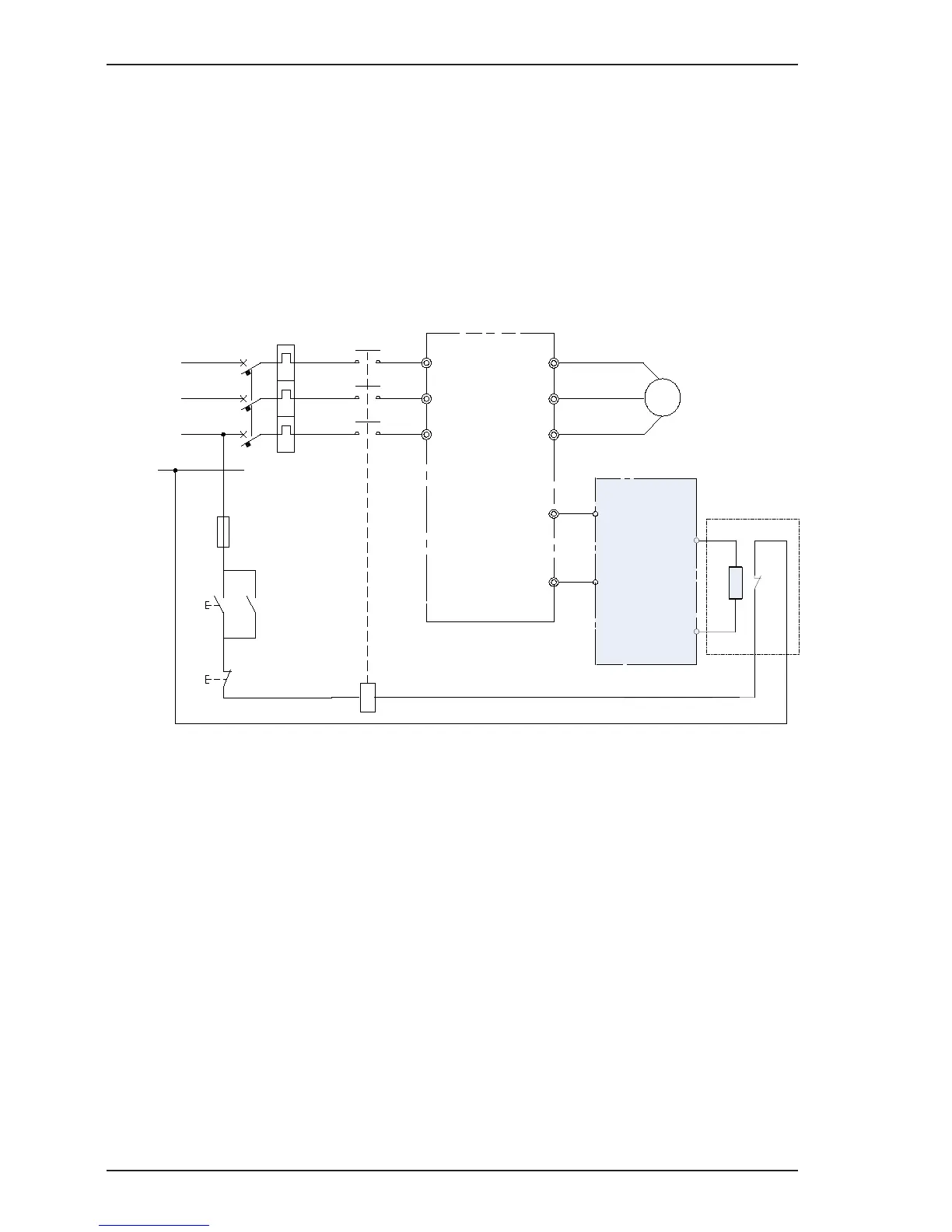
Figure 3-20 Basic wiring method 1
In this wiring method, the input voltage class of the contactor control coil is 220 VAC. The NC contact of the thermal
relay is connected to the power supply of the wire package driven by the main contactor. When a fault occurs, the
driving power supply of the contactor is cut off to disconnect the main contactor.

 Loading...