Options
‑85‑
Model A B W E D L T C F
185‑10 23 18.5 33.5 16.5 30 82 4.5 10.5 16.5
185‑12 12.8
185‑14 14.7
185‑16 16.7
185‑20 18.8 20.7 14.3
240‑10 26 21 37.7 18.0 32.0 88.0 5.0 10.5 17.0
240‑12 12.8
240‑14 14.7
240‑16 16.7
240‑20 20.7
300‑10 28.0 23.0 41.0 18.0 37.0 97.0 5.0 10.5 17.0
300‑12 12.8
300‑14 14.7
300‑16 16.7
300‑20 20.7
5.3.2 Selection of Control Circuit Cables
Note
Wire the control circuit cable according to EN 60204‑1.
To prevent peripheral interference and noise, shielded cables are recommended for
I/O signal cables. Connect both ends of the shield to the equipment 360 degrees using
signal shield support. Separate shielded cables should be used for different analog
signals, and shielded twisted pair cables are recommended for digital signal cables.
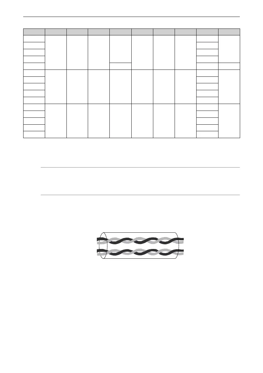
Figure 5‑15 Shielded twisted pair cable

 Loading...


