Terminals
‑88‑
To facilitate commissioning, additional pin with supply voltage (+24V) is integrated.
The bridging of the 24 V terminal to STO1/STO2 is needed in case the safety circuit is
installed but no STO function is needed.
Terminal descriptions
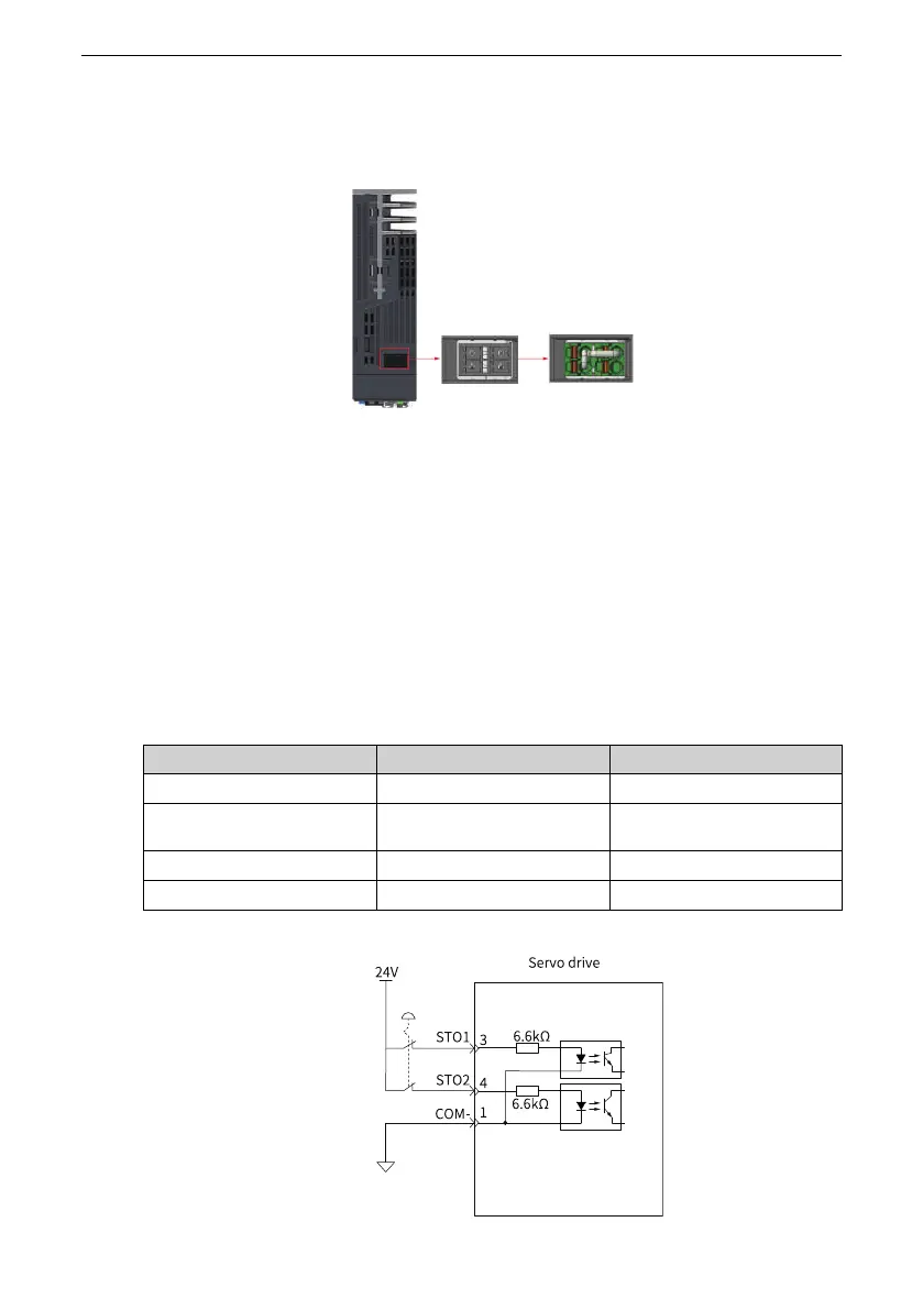
● Electrical specifications and connections of input circuit
This section describes the characteristics of the input signals assigned to the CN6
connectors.
■ Specifications
The servo drive operates normally only when the input states of STO1 and
STO2 are both "High" ("1" or "H").
The servo drive does not operate when the input states of STO1 or STO2 are
different or are both "Low" ("0" or "L").
■ Electrical characteristics of Safety Request Input Signal are as follows:
Item
Characteristics
Description
Voltage range
24V DC (±15%)
‑
Input current
3.6mA(Typ.)
This is the value per
channel.
Standards of logic levels "0" < 3 V, "1" > 15 V
‑
Digital input impedance
6.6 kΩ
‑
■ Connection example of external 24 V

 Loading...


