Terminals
‑89‑
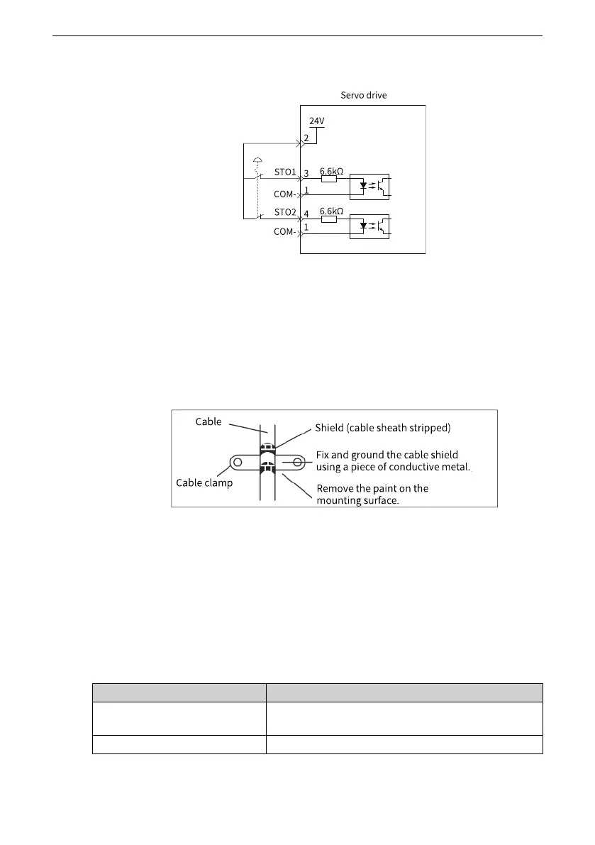
■ Connection example of internal 24 V
● EMC requirements
■ To avoid short circuit between two adjacent conductors, either use cable with
shield connected to the protective bonding circuit on each separate conductor,
or use flat cables with one earthed conductor between each signal conductor.
■ Double‑shielded or single‑shielded twisted multi‑pair cable is strongly
recommended.
■ Fix and ground the cable shield using a piece of conductive metal.
Example of cable clamp:
■ The maximum allowable cable length between the drive and the activation
switch is 30 m.
● Additional requirements
■ All wiring must be well protected, routed and clamped where practicable.
■ It must be assured that there is no pulling or pinching on the cable when
installing.
■ For cabling the DI inputs of the STO, to avoid common cause failure in the
cables, the two channels must be routed through two well‑apart routes, or the
cable must be protected with double‑shielded methods.
Cable
Description
Category
Low voltage, double‑shielded or single‑shielded
twisted multi‑pair cable
Maximum size
0.8 mm
2
(18 AWG)

 Loading...


