3-3
Installing to a Load Frame
Installation
Swivel Coupling
Do not load a swivel coupling with compressive force. Compressive forces
can damage the swivel coupling and load cell.
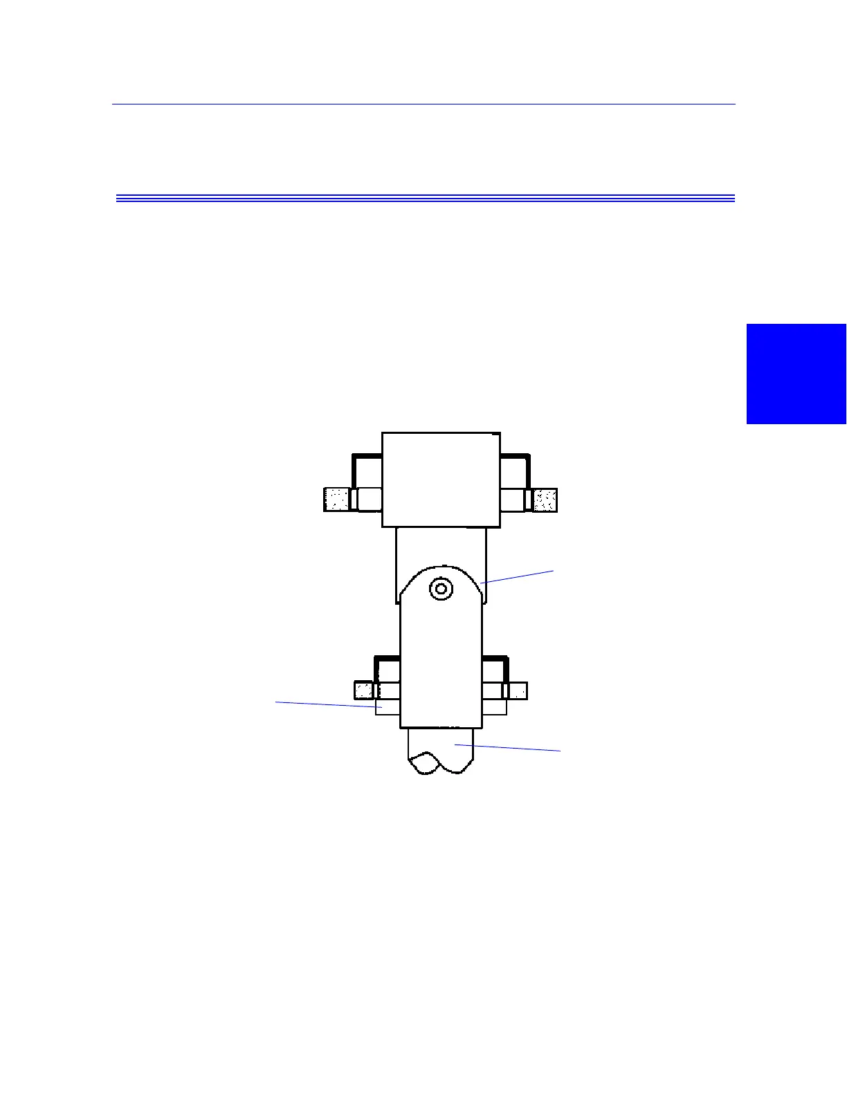
A swivel or flexible coupling, connects the upper grip to the load cell. Figure 3-2
on page 3-3 illustrates this coupling. The coupling consists of two clevis type
sockets, one on each end, coupled together by a coupling pin. The coupling allows
the grip to swivel from side to side to compensate for variances in the specimen or
load string alignment.
Threaded Couplings
Figure 3-3 on page 3-4 illustrates a threaded coupling. A threaded attachment kit
uses a female clevis socket which threads into the base plate, load cell or actuator
piston rod. You eliminate any end play by tightening a locknut against the actuator
piston rod or load cell, and the grip locknut against the grip adapter.
Figure 3-2. Swivel Coupling
Load cell
Coupling
Locknut
(Depending on grip)
Male grip end
 Loading...