2712-018 and 2712-020 M10-14179-EN
6-14
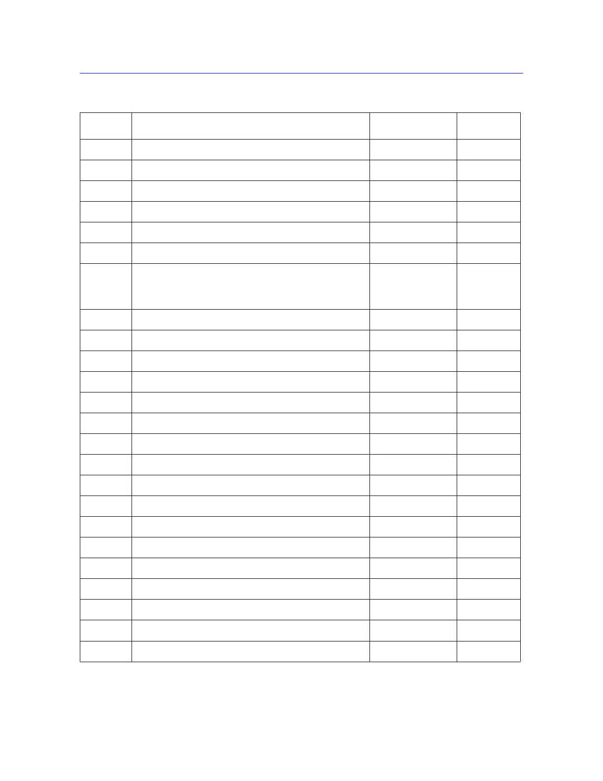
Table 6-4. 2712-018 and 2712-020 Parts List
Item Description Part Number Quantity
2 Lever and ball valve assembly A2-44 1
5 Piston T2-258 1
6 Roller wedge T2-259 2
7 Roller link T2-261 2
8 Jaw face holder (left side) T2-262 1
9 Jaw face holder (right side) T2-263 1
10 Multiplying link
2712-018
2712-020
T2-1038
T2-454
2
2
11 Quick clamp hose fitting T2-267 1
12 Seal backup 33-4-154 1
14 Valve cap T2-278 1
15 Adjustable lever guide T2-279 1
16 Valve handle T2-280 1
17 Valve seal T2-284 2
18 Hole cap T2-293 1
19 Conical spring T2-391 1
21 O-ring 33-2-23 1
22 Quad ring 33-5-1 1
23 Compression spring 66-2-10 2
26 Dowel pin (3/16 x 7/16 in) 705B69 4
27 Dowel pin (3/16 x 3/4 in) 705B74 2
28 Dowel pin (3/16 x 5/8 in) 705B72 5
29 Dowel pin (1/8 x 1/2 in) 705B40 1
30 Cap screw (10-24 x 1/2 in) 201G42 4
31 Screw (4-40 x 3/8 in) 201G2 2
 Loading...