29
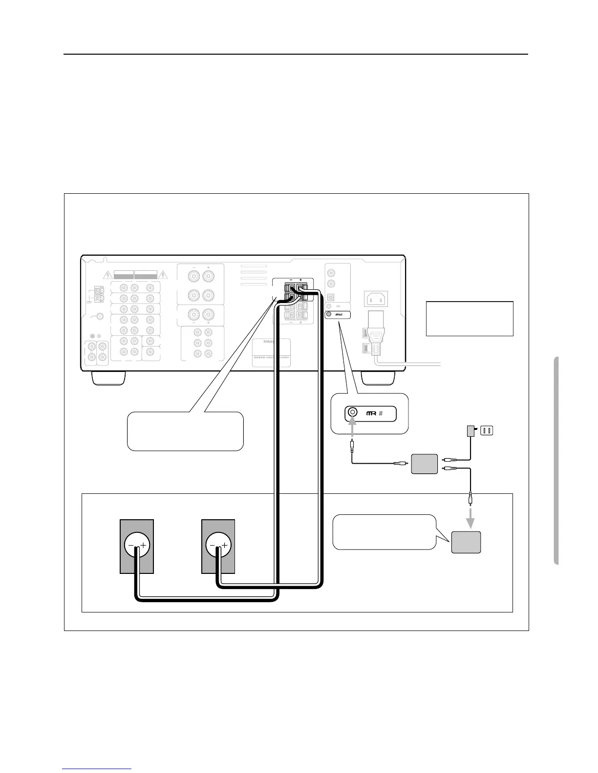
SUB ROOM
2
Remote sensor
HR-600
HB-100
Connecting block
Power supply
120 V AC
(Unswitched)
Right speaker
when seen from the front
Locate a Remote Sensor
in the sub-room.
Left speaker
when seen from the front
GND
AM
FM
75
ANTENNA
C
D
PHONO
R
L
(
PLAY
)
(
REC
)
OUT
I
N
MONITOR
OUT
SUBWOOFER
PRE OUT
DVD
TAPE
VIDEO 1
VIDEO 2
VIDEO 3
I
N
I
N
I
N
OUT
I
N
R
L
V
R
L
V
REMOTE CONTROL
OPTICAL
COAXIAL 1
COAXIAL 2
SURROUND
CENTER
SPEAKER
SUB
WOOFER
MULT
I
CHANNEL I
NPUT
FRONT
CENTER
SURROUND
SPEAKERS
CAUTION: SPEAKER IMPEDANCE
6 OHMS MIN. PER EACH
SPEAKER TERMINAL
RATING:
AC120V 60Hz 3.9A
AV RECEIVER
MODEL NO. DTR-5
MANUFACTURED IN MALA
YSIA
2-1, NISSHIN-CHO, NEYAGAWA-SHI,OSAKA,
JAPAN
R
L
R
L
R
R
L
L
R
L
R
L
R
L
R
L
DIGITAL INPUT
FRONT
SPEAKERS
A
FRONT
SPEAKERS
B
WARNING
RISK OF ELECTRIC SHOCK
DO NOT OPEN
RISQUE DE CHOC ELECTRIQUE
NE PAS OUVRIR
AVIS
AC I
NLET
AC 120V 60Hz
SWITCHED
TOTAL 120W 1A MAX.
DTR-5
1
Connect speaker cables for
the sub-room to the FRONT
SPEAKERS B jacks.
Connection example of
Onkyo Multi-room
System Kit HKT-600
Enjoying Music and Movies in the Sub-room
Outline of Multi-room Remote System
If you connect Onkyo Multi-room Remote System components as shown in the figure below, you can control the components from an adja-
cent sub-room as well as from the room where the DTR-5 is located.
The following equipment (sold separately) is essential for using the Onkyo Multi-Room System:
•
Onkyo’s Multi-Room System kits HKT-600 or HKT-700 (IR Remote Controller Extension System), or
•
Multiroom A/V distribution and control systems from Niles
®
and Xantech
®
to name a few
Connections in the Sub-room
Make connection as shown below. Do not plug the equipment into the power source until the connection is complete.