8XC251SA, SB, SP, SQ USER’S MANUAL
8-6
Timer 1 is controlled by the four high-order bits of the TMOD register (Figure 8-5) and bits 7, 6,
3, and 2 of the TCON register (Figure 8-6). The TMOD register selects the method of timer gating
(GATE1), timer or counter operation (T/C1#), and mode of operation (M11 and M01). The
TCON register provides timer 1 control functions: overflow flag (TF1), run control (TR1), inter-
rupt flag (IE1), and interrupt type control (IT1).
Timer 1 operation in modes 0, 1, and 2 is identical to timer 0. Timer 1 can serve as the baud rate
generator for the serial port. Mode 2 is best suited for this purpose.
For normal timer operation (GATE1 = 0), setting TR1 allows timer register TL1 to be increment-
ed by the selected input. Setting GATE1 and TR1 allows external pin INT1# to control timer op-
eration. This setup can be used to make pulse width measurements. See section 8.5.2, “Pulse
Width Measurements.”
Timer 1 overflow (count rolls over from all 1s to all 0s) sets the TF1 flag generating an interrupt
request.
.
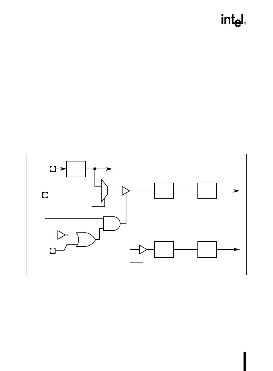
Figure 8-4. Timer 0 in Mode 3, Two 8-bit Timers
A4112-02
GATE0
INT0#
TR0
TL0
(8 Bits)
TF0
Interrupt
Request
12
T0
Overflow
XTAL1
TF1
Overflow
TH0
(8 Bits)
TR1
1/12 F
OSC
Interrupt
Request
1/12 F
OSC
C/T0#
0
1