EasyManua.ls Logo

Intel Celeron D User Manual

Intel Celeron D
64 pages
To Next Page IconTo Next Page
To Previous Page IconTo Previous Page
Page #9 background image
Intel
®
Celeron
®
D Processor in the 775-Land LGA Package Thermal Design Guide9
Order #303730
Processor Thermal/Mechanical Information
2.0 Processor Thermal/Mechanical
Information
2.1 Mechanical Requirements
2.1.1 Processor Package
The Celeron D Processor in the 775-Land LGA Package is packaged in a Flip-Chip Land Grid
Array (FC-LGA4) package that interfaces with the motherboard via a LGA775 socket. Please refer
to the processor datasheet for detailed mechanical specifications.
The processor connects to the motherboard through a land grid array (LGA) surface mount socket.
The socket contains 775 contacts arrayed about a cavity in the center of the socket with solder balls
for surface mounting to the motherboard. The socket is named LGA775 socket. A description of
the socket can be found in the LGA775 Socket Mechanical Design Guide.
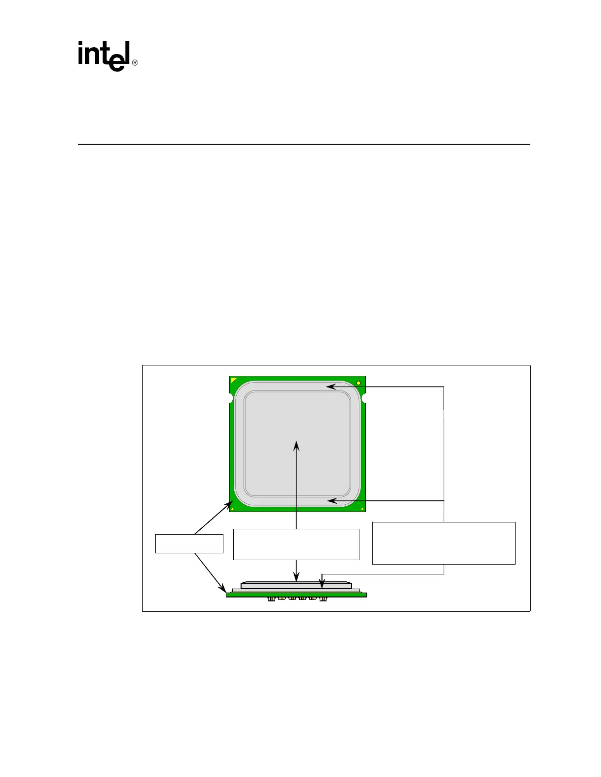
The package includes an integrated heat spreader (IHS) that is shown in Figure 1 for illustration
only. Refer to the processor datasheet for further information. In case of conflict, the package
dimensions in the processor datasheet supercede dimensions provided in this document.
The primary function of the IHS is to transfer the non-uniform heat distribution from the die to the
top of the IHS, out of which the heat flux is more uniform and spread over a larger surface area (not
the entire IHS area). This allows more efficient heat transfer out of the package to an attached
cooling device. The top surface of the IHS is designed to be the interface for contacting a heatsink.
Figure 1. Package IHS Load Areas
Top Surface of IHS
to install a heatsink
IHS Step
to interface with LGA775
Socket Load Plate
Substrate
Top Surface of IHS
to install a heatsink
IHS Step
to interface with LGA775
Socket Load Plate
Substrate

Table of Contents

Question and Answer IconNeed help?

Do you have a question about the Intel Celeron D and is the answer not in the manual?

Intel Celeron D Specifications

General IconGeneral
Processor FamilyIntel Celeron D
ArchitectureNetBurst
Number of Cores1
SocketLGA 775
FSB Speed533 MHz
Operating Voltage1.25V-1.4V
Virtualization TechnologyNo
Integrated GraphicsNo
Core NamePrescott
Core SteppingD0
Clock Speed3.6 GHz
L1 Cache16 KB
Process Technology90 nm
Instruction SetSSE, SSE2, SSE3
L2 Cache256 KB - 512 KB

Summary

Introduction

Importance of Thermal Management

Ensures components operate within their functional temperature range for optimal performance and prevents damage.

Processor Thermal/Mechanical Information

Heatsink Attach

Describes general guidelines and requirements for attaching a heatsink to the processor package.

Heatsink Design Considerations

Covers key parameters for heatsink design: surface area, conduction path, and heat transfer.

Thermal Metrology

Characterizing Cooling Performance Requirements

Defines thermal characterization parameters (Psi) to evaluate thermal solution performance.

Local Ambient Temperature Measurement Guidelines

Provides guidelines for accurately measuring local ambient temperature around the processor.

Processor Case Temperature Measurement Guidelines

Describes procedures for accurately measuring processor case temperature (Tc) on the IHS.

Thermal Management Logic and Thermal Monitor

Thermal Monitor Implementation

Details the on-die thermal management features: PROCHOT#, TCC, and registers.

Operation and Configuration

Covers enabling, configuring, and monitoring the Thermal Control Circuit (TCC).

How On-Die Thermal Diode, TCONTROL and Thermal Profile Work Together

Explains the interaction of thermal diode, TCONTROL, and thermal profile for fan speed control.

LGA775 Socket Heatsink Loading

LGA775 Socket Heatsink Considerations

Discusses heatsink clip load for mechanical performance and thermal interface.

Heatsink Clip Load Metrology

Thermal Interface Management

Case Temperature Reference Methodology

Thermocouple Attach Procedure

Provides step-by-step instructions for conditioning and attaching a thermocouple to the IHS.

Board Level PWM and Fan Speed Control Requirements

Related product manuals