16
(6) Hard disk activity LED: HD LED
This header connects to the hard disk activity indicator light on the case.
(7) Reset switch: RESET
This 2-pin header connects to the case-mounted reset switch for rebooting your
computer without having to turn off your power switch. See the figure below.
(8) Power switch: PWR BTN
This 2-pin header connects to the case-mounted power switch to power
ON/OFF the system.
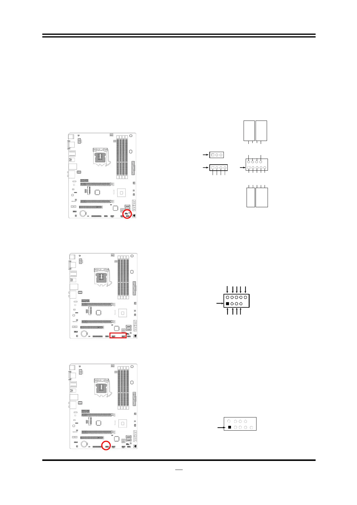
System Case Connections
HDLED
RESET
VCC5
GND
VCC5
PWR LED
PWRBTN
PWRBTN
PWRLED
HDDLE
RSTSW
NC
GND
JW FP
Pin 1
SPEAK
SPKR
GND
NC
VCC5
Pin 1
PWRLED
Pin 1
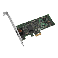
(9) USB 2.0 Port Headers (9-pin): USB1/USB2
These USB 2.0 headers are used for connecting the additional USB 2.0 port
plugs. By attaching an option USB 2.0 cable, your can be provided with two
additional USB 2.0 plugs affixed to the back panel.
USB Port Header
Pin 1
VCC
-DATA
GN
+DATA
VCC
OC
-DATA
GND
+DATA
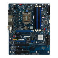
(10) Serial COM Port header(9-PIN): COM1
COM1 is a 9-pin RS232 connector.
Serial COM Port 9-pin Block
Pin1