5
1. Installation
1 2 3 4 5
6
7
8
9
10
11
12
13
14
15
232425
16
17
18 20
19
25 24 23
22
21
20
19
18
17
16
15
14
13
12
11
10
9
8
7
6
5
4
3
2
1
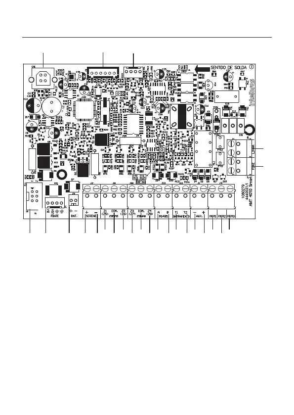
1. Connector for connection to the XEG 4000 Smart, XG 4000 Smart or XE 4000 Smart board
2. Connector for power supply from the switched-mode power supply
3. Battery connector
4. Positive of the siren output
5. Negative of the siren output
6. Zone 1 input for connecting wired sensors
7. Common for connecting wired sensors (from Z1 and Z2 zones)
8. Zone 2 input for connecting wired sensors
9. Zone 3 input for connecting wired sensors
10. Common for connecting wired sensors (from Z3 and Z4 zones)
11. Zone 4 input for connecting wired sensors
12. Terminal A for the RS485 digital bus (used to control keyboards, wireless device
receivers, zone and PGM expanders)