37
INSTALLING THE ACU
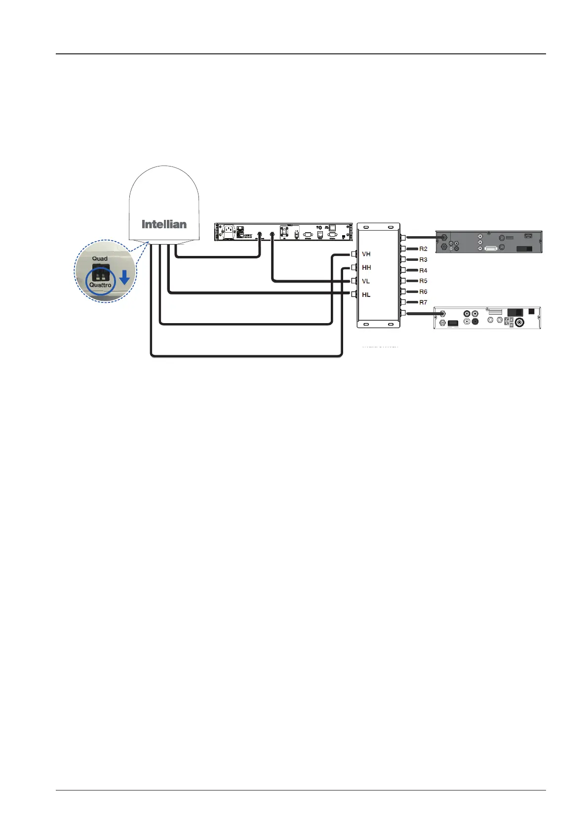
RF 1 (VL)
ACU
RF 2 (HL)
RF 3 (VH)
RF 4 (HH)
4x8
Multi Switch
QSM/ Quattro mode
Receiver 8
Receiver 1
Figure 04. Multi-Switch Connection Conguration
• Be sure to set the QSM to Quattro mode.
• Connect the RF cable from the ACU's RF1 connector on the power switch
box located inside of the radome to the ANT. RF1 connector on the rear of
the ACU.
• Connect the RF cable from the RECEIVER's connector on the rear of the
ACU to the RF on the IRD through the Multi-switch as shown gure above.
• Connect the ship’s gyro cable from the ship’s gyro to the Ship’s Gyro
connector on the ACU.
• Connect the power cable from the AC power connector on the rear of the
ACU to a power source at 110- 220 V AC.
• Press the POWER ON switch on the rear of the ACU to power on the
antenna.
 Loading...