TL6000, Users
Rev L, June 2008
Page 15 of 22
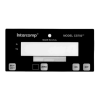
1. Press the ON switch. The display does a lamp test; during this time the scale does a
quick check of itself. Then the weighing system starts weigh mode.
2. Intercomp recommends that you allow the electronics to operate for three minutes
after first turning the power on. This allows the electronics to become stable for
maximum accuracy before you check the calibrations.
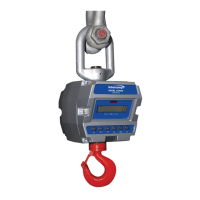
3. Make sure no weight is on the hook. Press the ZERO key. Press the TARE and
ZERO key to clear tare. The weight shown is zero.
4. Apply weights throughout the weighing range, and verify the correct weight is
displayed at each step. (+/- 0.1% of applied load or ± 1 division, whichever is greater
for scales 500 – 10000 lbs and ±0.2% of applied load or ± 2 divisions, whichever is
greater for scales 25000 lbs or greater)
5. Remove weights and verify the display returns to zero.
6. If there is a failure to meet any of the conditions above, please refer to the
Calibration Procedure.
7. When all the conditions above are correct, the scale is operational.
How to enter a number
During this routine you will be asked to enter numbers at many points. The scale will
show a number (originally all zeros) with a blinking digit. At this point the commands listed
at the sides of the keys become active. Press the UP and DOWN arrow keys to increase
and decrease the blinking digit. Press the LEFT and RIGHT arrow keys to move to other
digits. Press the ZERO and PEAK keys together to save the value and advance to the
next parameter.
Five point span
The scale has a five point calibration feature that reduces the effects of non-linearity in
the load cells. This requires that you place five weights on the cell during calibration.
The first weight must be greater than zero, the second greater than the first, the third
greater than the second, the fourth greater than the third, and the final weight
somewhere between the fourth and the capacity. To use less than five calibration
points, turn the scale off before reading the next cal point.
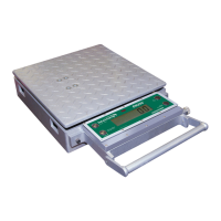
Calibration Strap
The calibration header that uses the calibration shorting strap is located on the bottom
side of the circuit board (opposite side of the display). This 90° header is labeled CAL.
Enabling the calibration.
The first four parameters may be edited with or without the calibration strap. To
perform the actual weight calibration, you must remove the calibration blocking
strap. Remove the 4 screws on the back plate of the tension link. Remove back
plate. The calibration header is located on the lower right corner of the circuit
board. Remove the black shorting strap and slide it on one of the pins (for
convenience). Screw the back plate back on.