Do you have a question about the Intercomp SW500 and is the answer not in the manual?
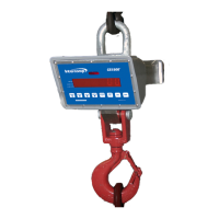
Lists and describes available optional accessories for the SW500 Wired Scale System.
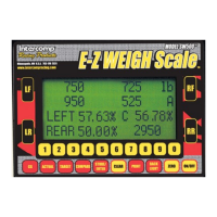
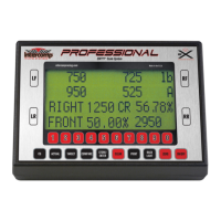
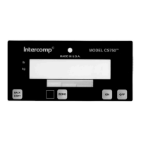
Details the function of various keys and the display screen of the indicator.
Provides information on voltage, battery life, filtering, and input/outputs.
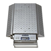
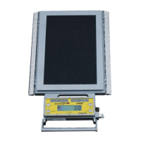
Details speed, accuracy, and division (capacity/graduation) for different scale models.
Lists humidity and temperature operating and storage ranges for the scale system.
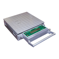
Details dimensions and weight for various scale models and the carrying case.
Explains the function of individual keys like ON/OFF, ZERO, BACKLIGHT, PRINT, etc.
Describes how to turn the indicator's backlight on and off.
Details how to print the screen and configure serial output settings.
Explains how to erase memory locations or reset numeric entries.
Describes using the key to store setups as targets or save numeric entries.
Explains how to compare actual weight against a target weight.
Describes how to view the ideal weight setup for a car.
Explains how to view the currently measured weight.
Details how to access and calculate Standard and Vertical CG.
Explains using the keypad for number entry and recalling setups.
Describes keys used in Road Racing format to select/unselect scales.
Explains combinations for switching units, read-only mode, and hub mode.
Instructions on changing the default display format upon startup.
How to set a specific display format to appear after power-up.
Explains storing and manually entering target weight setups.
Procedure for storing up to 99 weight setups as target setups.
Steps for entering target weights using the Direct Key-In format.
Details entering target weights via Wedge and Target % formats.
Explains entering target weights based on percentages.
Procedure to recall stored target setups using the numeric keypad.
Procedure to clear a specific setup from memory or clear all setups.
How to adjust the display contrast using backlight and wheel keys.
Instructions for connecting and setting up the wired scale system.
Guide to arranging scales, turning on the indicator, and selecting display format.
Explains the content and structure of the different display lines.
Procedure for compensating weight differences in Hub Plate systems.
Steps to enable Hub Mode and enter Tire Assembly and Hub Plate weights.
Explains how the system measures tire force and performs calculations.
Illustrates representative displays for Oval Track, CUP/NW, and Road Racing modes.
Illustrates representative displays for Dirt Track and Drag/Rally modes.
Illustrates representative displays for Total and Total + 4 modes.
Explains how the system measures kart tire force and performs calculations.
Illustrates representative displays for Oval Track, Kart, Road Racing, and Dirt Track modes.
Illustrates representative displays for Drag/Rally and Wheels & Percentages modes.
Describes the display format for motorcycle applications.
Introduces access to Japan and RF Minus LF Cross display formats.
Explains how to select between Free Scaling and Fixed Scaling.
Describes the display format for individual weights, percentages, and totals.
Describes the display format for front end, left side, cross percentage, and total weight.
Explains the RF Weight minus LF Weight calculation and display.
Illustrates CG scenarios based on weight distribution on tires.
Details measuring axle width and wheel base for CG calculation.
Explains how CG results are displayed and how to return to the weight screen.
Explains the theory of Vertical CG and how car elevation affects it.
Step-by-step guide to calculating Vertical CG, including measurements.
Describes multi-line print output and provides an example.
Describes transmitting total weight continuously at a high frequency.
Details the 13-line data transmission format and data identifiers.
Explains using the stereo jack for RS-232 output and its pinout.
Details connecting the indicator to a computer via USB and driver requirements.
Lists and defines scale and indicator error messages for troubleshooting.
Information on replacing batteries and battery life for the indicator.
Explains the auto-off feature to conserve battery power.
| Platform Size | 19.7" x 19.7" |
|---|---|
| Auto Shut-off | Yes |
| Display | LCD |
| Power | Battery or AC adapter |
| Power Supply | 4 AA batteries or AC adapter |
| Units | lb / kg |
| Operating Temperature | 32°F to 104°F (0°C to 40°C) |