SW500 Wired Scale System
700431
Rev G, December 2021
Page 19
SETUP
SYSTEM CONFIGURATION
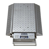
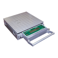
ATTENTION: If using the Precision Hub Plate Scale, refer to the Hub Plate
Scale user manual and the Quick Start Hub Mode instructions set forth in the
Operation section.
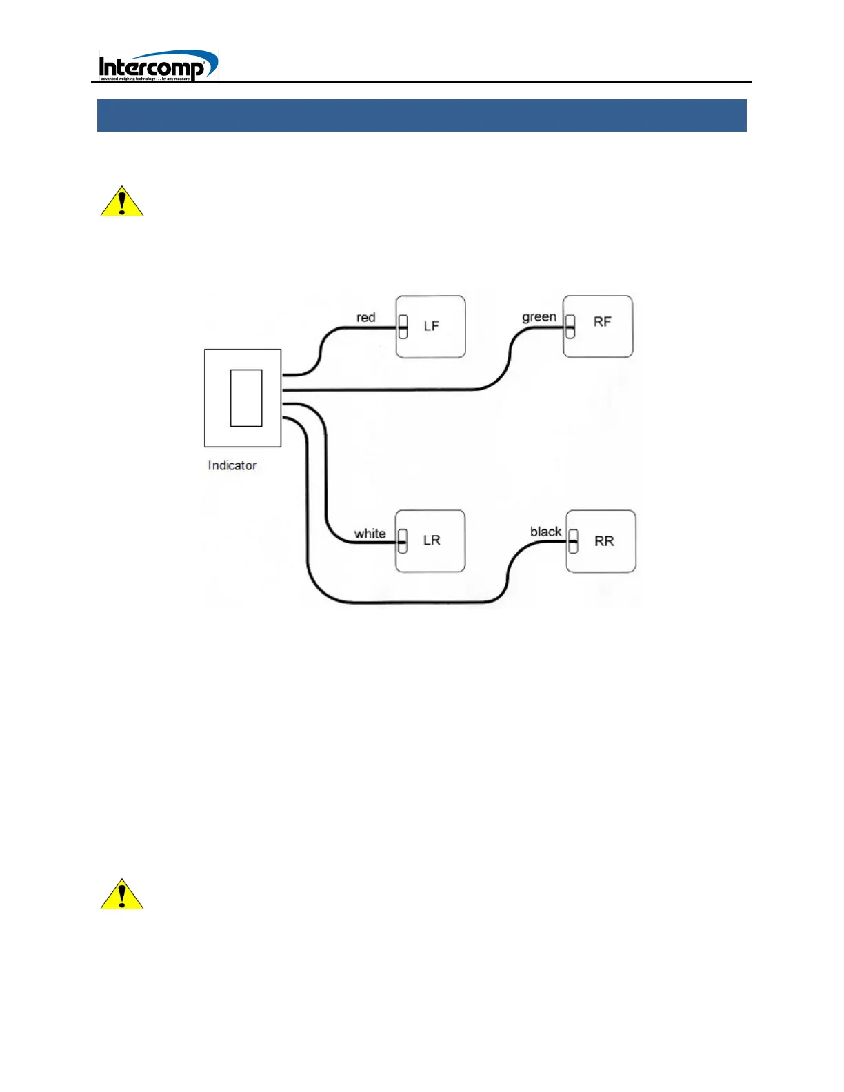
WIRED SYSTEM SETUP CONFIGURATION DIAGRAM
1. Position each of the four scales near the car tire using the following guide. LF by
Left Front, RF by Right Front, LF by Left Rear and RR by Right Rear. Turn all of the
scales on.
2. Connect one end of each cable to the scale as depicted in the system configuration
diagram: LF-Red cable, RF-Green cable, LR-White cable, RR-Black cable.
3. Turn the indicator on. If the scale readings are not zeroed, press the ZERO key.
4. Jack the car onto each scale. If the optional ramps are available, position a ramp
and scale in front of each tire. Slowly drive the vehicle onto the scales.
5. When the vehicle is positioned on the scales, refer to the Overview procedure in the
Operation section to set up the system to display the desired readings
ATTENTION: When in set in Motorcycle Mode and using motorcycle scale sets,
use the LF (red cable) for the Front tire, and the LR (white cable) for the Rear
tire. Refer to the Special Display section for motorcycle applications.