14 NX-595E Installation Manual
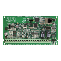
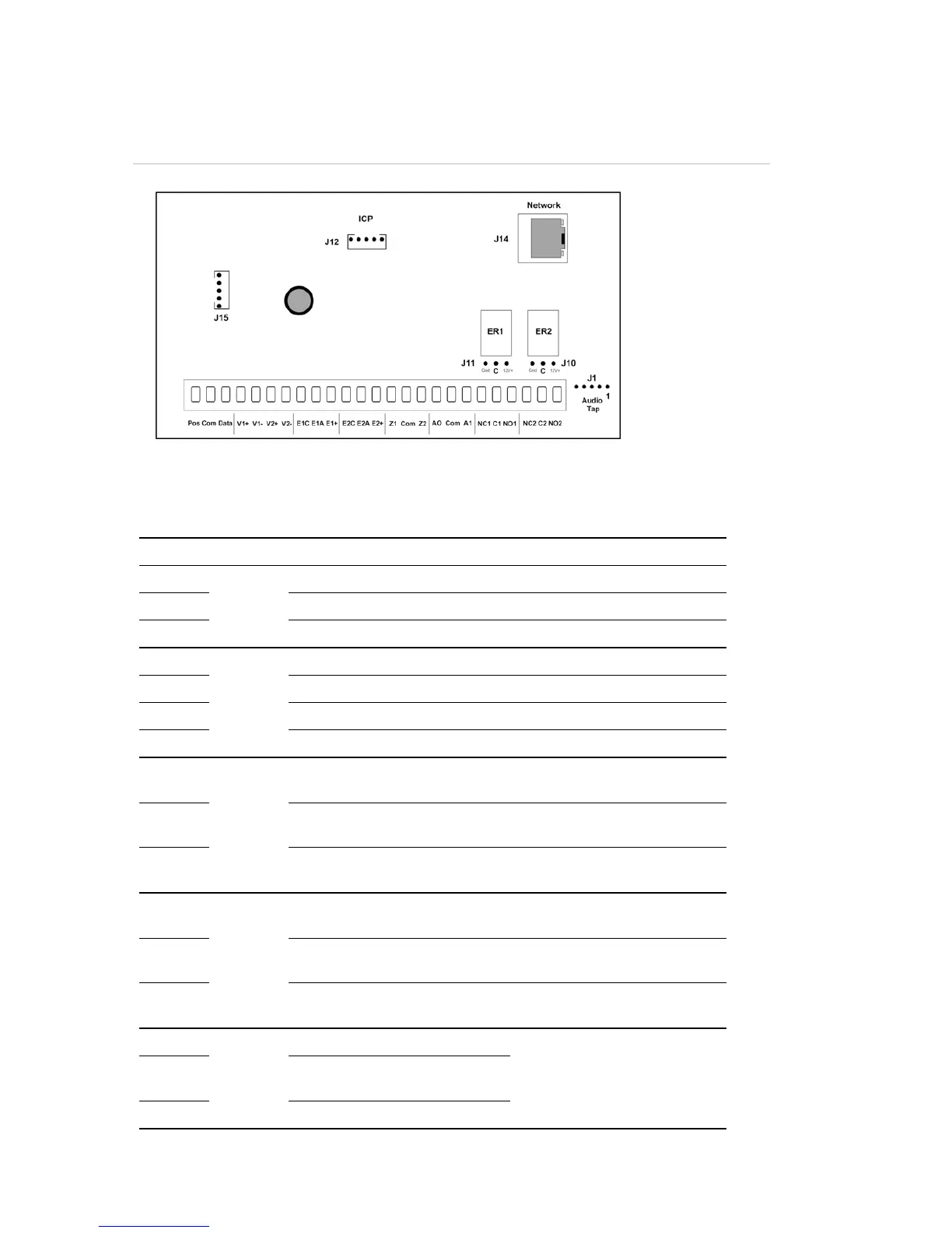
PCB Layout
Figure 7
Terminal descriptions
Terminal Description
1 Pos
Panel
Bus
Positive terminal on the NetworX panel
2 Com Common terminal on the NetworX panel
3 Data Data terminal on the NetworX panel
4 V1+
NX-181xx
Audio
Lines
Audio Line A, positive Green / White
5 V1- Audio Line A, negative Green
6 V2+ Audio Line B, positive Orange / White
7 V2- Audio Line B, negative Orange
8 E1C
Entrance
camera 1
Common terminal on outdoor
station 1
Yellow
9 E1A Audio terminal on outdoor
station 1
Red
10 E1+ Positive terminal on outdoor
station 1
Blue
11 E2C
Entrance
camera 2
Common terminal on outdoor
station 2
Yellow
12 E2A Audio terminal on outdoor
station 2
Red
13 E2+ Positive terminal on outdoor
station 2
Blue
14 Z1
Additional
Zones
1
st
/ 3
rd
Zone 3K3 = Single EOLs
3K7 = Low zones
6K9 = High zones
15 Com Common (-) return for Zone
loop
16 Z2 2
nd
/ 4
th
Zone
USBUP