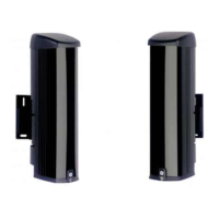
When the detectors are placed one on the top of the other (see Figure 9 below),
allocate the same channel to each detector and relay them to each other by the
synchronization link in Column mode.
Figure 9: Single channel example
(1)
(1)
(2) (2
(1) Channel 1 (2) Inter-module connection
Operating modes
The SB450-N and SB4100-N barriers can operate in 2 modes:
• “AND” mode: simultaneous obscuration of 2 dual-beam cells to trigger the
intrusion alarm.
• “OR” mode: obscuration of one of the dual-beam cells to trigger the intrusion
alarm.
The mode is selected with DIP switches 3 to 5. The DIP switch location is shown
in Figure 5 on page 6.
See Figure 10 on page 12 for modes illustration and DIP switch settings.
Caution: The DIP switches settings must be identical on both of 2 associated
modules. In OR mode, the response time must be also equal.
SB Series AIR Beam Detectors In
stallation Manual 11