12
iScan 180 Auto Switch Module
Installation
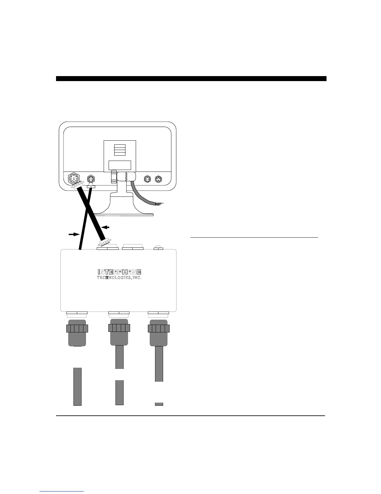
The black box that came with your iScan 180 is called the
iScan 180 Auto Switch Module (ASM). It houses the switches
that control which phased array is being used.
1) Select a location to mount the ASM. Keep in mind that
the unit must be protected from from moisture and
extreme temperatures. Also, you will need to route the 10’
Transducer and Master Control cables to the display
location.
2) Connect the 4-Pin Master Control Cable to the
corresponding 4-Pin connector on the back of the iScan
180 display.
3) Connect the 9-Pin Master Display Cable to the
corresponding 9-Pin connector on the back of the iScan
180 Dispaly.
4) Connect the three transducer cables to the matching ports
on the back panel of the ASM:
Cable Label Panel Label Cable Band
PORT - HORZ PORT -HORZ BLACK
STBD - HORZ STBD - HORZ BLUE
STBD - VERT STBD - VERT GREEN
The 30 foot, 9-Pin Remote Display and the 30 foot 4-Pin
Remote Control Cable ports are only used with the iScan 180
Remote Station Kit (RSK). These cables are included with the
RSK.
The ASM must be located where the 10 foot Master Control
Cable and the 10 foot Transducer Control Cable can be
connected to the iScan 180 display.
NOTE: The ASM is not submersible. It should be placed in a
location where it is not subject to immersion in water.
MASTER
DISPLAY
REMOTE
DISPLAY
MASTER
CONTROL
CABLE
REMOTE
CONTROL
CABLE
iSCAN 180 AUTO SWITCH
MADE IN U.S.A.
TRANSDUCER
STBD - VERT
TRANSDUCER TRANSDUCER
STBD - HORZ PORT - HORZ
STBD - VERT
GREEN
STBD - HORZ BLUE
PORT - HORZ
BLACK
10 FOOT, 9-PIN MASTER
DISPLAY CABLE
10 FOOT
4-PIN
MASTER
CONTROL
CABLE