6
Installation
Display Unit
The compact size of the iScan 180 display unit allows for easy
installation in almost any vessel. To get maximum
performance and life from your unit, the following guidelines
should be considered when selecting a mounting location:
1) Select a location where the unit is protected from excessive
temperatures. Heat is one of the worst enemies of electronic
components, and will accelerate component aging, thereby
reducing the trouble-free life of your iScan 180.
2) Mount the display in a location where it will be convenient
to route the power cord and transducer cable.
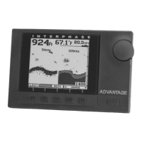
Power connection
The iScan 180’s power leads are the red and black wires inside
the cable that connects to the rear mount. These wires must be
connected to a source of 12VDC voltage. The red wire should
connect to the plus (+) 12 VDC and the black wire should be
connected to the minus (-) side of the 12 VDC.
To minimize electrical interference, carefully route the power
cable so that it does not run parallel or close to the transducer
cable, engine, refrigeration, bilge pump or any other critical
wiring. An in-line fuse holder is included with your unit and
should be placed in the positive lead as shown at left. A 2
Amp fuse is included.
IMPORTANT: The iScan 180’s 12 VDC power leads should
go directly to the boat’s battery, distribution board, or breaker
panel. Instability of the display may result if the unit has to
share leads with other electrical systems aboard your boat.
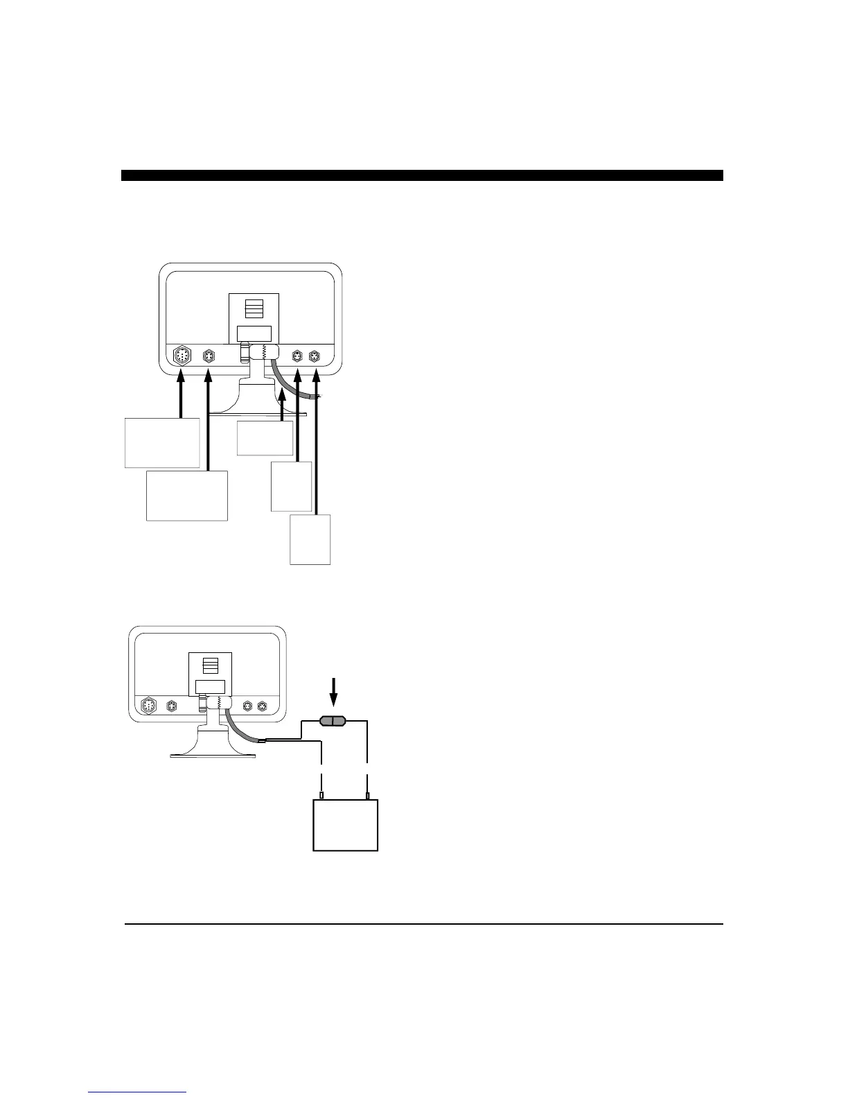
Wiring for Power & Transducer Connectors
The correct pin-out wiring sequences for the transducer
connectors are shown at right. DO NOT SHORTEN THE
TRANSDUCER CABLES. If a transducer cable longer than
the 30’ length supplied with your unit is needed, please contact
your Interphase dealer. 30-foot scanning sonar transducer
extension cables are available. (P/N 04-0014-008)
DANGER: Removal of any connector, disassembly of
transducer, shortening of any cable or use of any cable other
than that supplied by Interphase will void your warranty.
(-) (+)
12 VDC
iScan 180 Rear Panel Connections
Master
Display Input
9-Pin
Master
Control Cable
4-Pin
Power and
I/O Cable
Video
Input
3-Pin
2 Amp
In-Line Fuse
Black
Red
Video
Output
2-Pin