11
Version 1.0 (11/2007) en
Original language
RollerDrive EC200
Product information
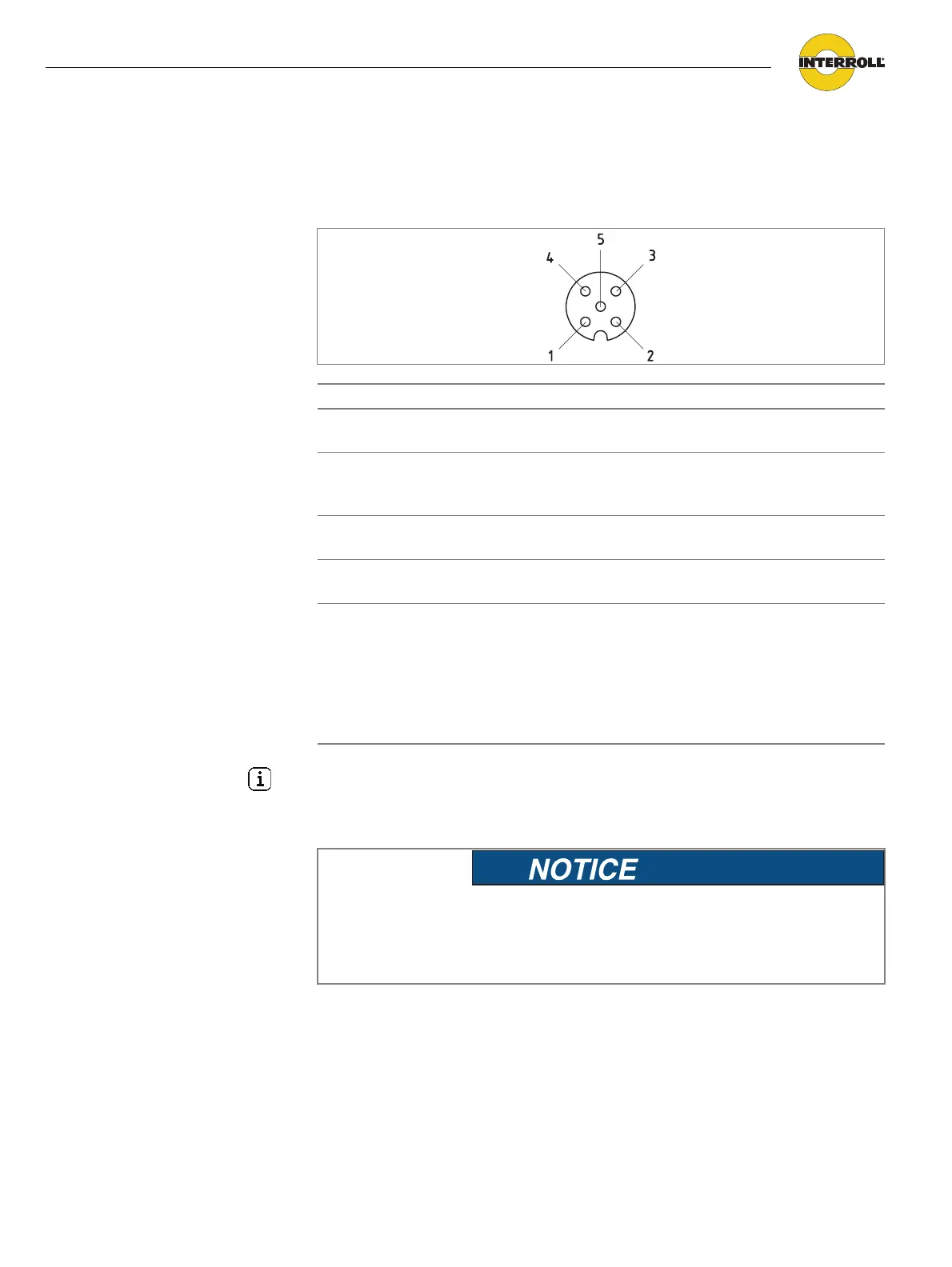
Motor plug
Pin Color Function Value
1 brown Power input from
power supply (+)
Nominal: 24 VDC
Range: 18 to 28 VDC
2 white Rotation direction,
seen from cable end
of the RollerDrive
Low U < 0.8 V = ccw
High U > 2.4 V = cw
3 blue Ground for power
and signal (-)
Ground
4 black Failure output Low = no failure
High = failure
5 gray Speed/start signal
analog
Range: 0 to 24 VDC
Stop (brake): 0 to 2 VDC
Speed: 2.4 VDC to 5 VDC
(Incline ratio: 1 V ~ 114.6 revs/min / gear
ratio)
Max. speed: 5 VDC to 24 VDC
(also see "Speed settings", page 12)
Hint
In case the RollerDrive is not directly connected to the refering DriveControl or
the Interroll extension cable, connect the motor plug by use of a Lumberg Fixcon
Coupling 5-FKT.
Pins 1 and 3 are not protected against incorrect
polarity connection.
Damage to the motor.
¾ Ensure the correct polarity.