13
Version 2.1 (08/2013) en
Translation of the original instructions
RollerDrive EC310
Product information
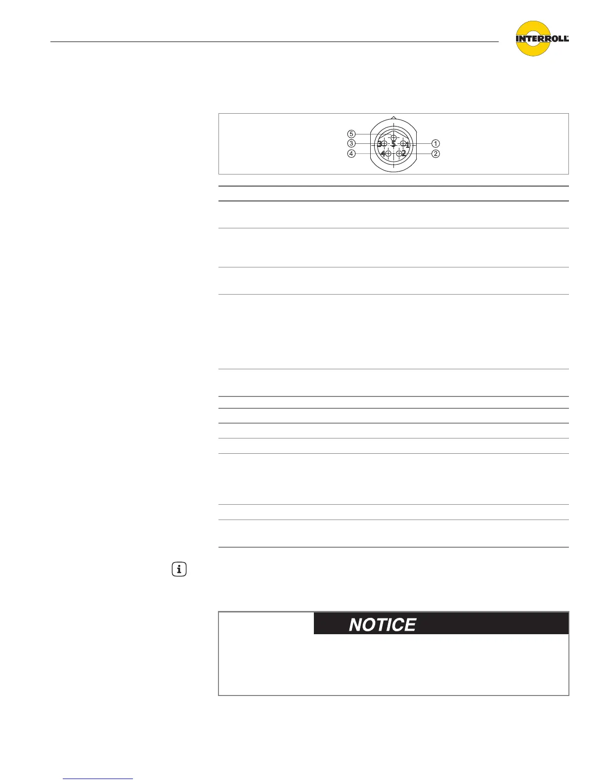
Motor plug
Pin Color Function Value
1 brown Power supply input (+) Rated voltage: 24 VDC
Voltage range: 18 to 28 VDC
2 white Direction of rotation,
seen from the cable end
of the RollerDrive
U < 4 V = counter clockwise
U > 7 V = clockwise
3 blue Earth for power supply
and signal (-)
Ground
4 black Fault output Open Collector
U
cesat
= 0.5 V for I
c
= 5 mA
U
max
= 30 V
I
cmax
= 5 mA
Error: Signal low
No fault: Signal high
5 gray Analogue speed/start
signal
see table below
Analogue speed/start signal (Pin 5)
Voltage range 0 to 24 VDC
Stop (braked state) 0 to 2.3 VDC
Speed 2,3 VDC to 10 VDC
(Incline rate above 2.3 VDC: 740 rpm (motor
revolutions)
linear between 2.3 and 10 VDC)
Max. speed 10 VDC to 24 VDC
The conveyor speed is calculated from the gear ratio and the nominal value.
(also see "Speed settings", page 11)
Hint
In case the RollerDrive is not directly connected to the corresponding
DriveControl or the Interroll extension cable, connect the motor plug using a
Conec M8 snap-in coupling.
Pins 1 and 3 are not protected against incorrect
polarity connection.
Damage to the motor.
Ensure the correct polarity.