46
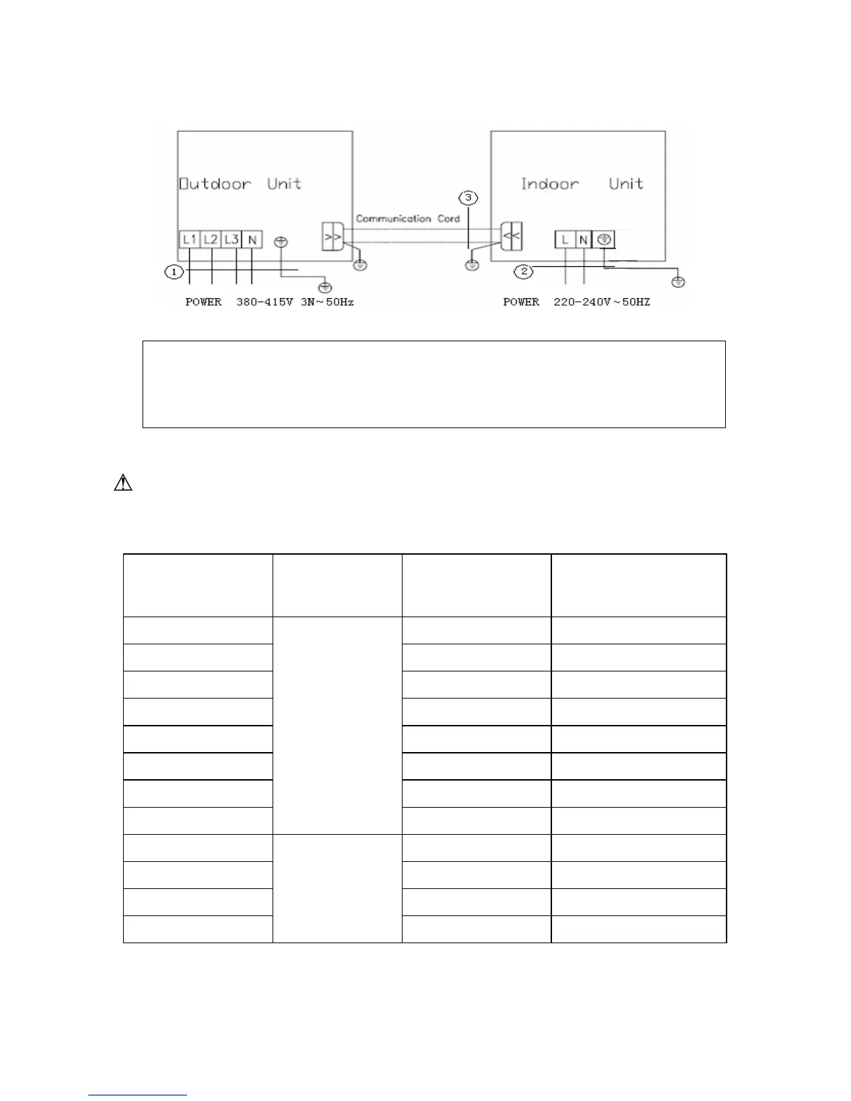
Fig.55
1.Power cord 5×4 mm2(H07RN-F) 2.Power cord 3×1.5 mm2(H05VV-F)
3.Communication Cords
The following table recommended by the model selection manual is about how to select the air
switch and power cable.
Warning! :
The section area of cables selected by users must not be smaller than the specifications shown in
the table below
Table.8
Model Power Supply
Capability of Air
Switch(A)
(Outdoor/Indoor)
Minimum Sectional Area
Of Earth Wire (mm2)
(Outdoor/Indoor)
16/6 2.5/1.0
16/6 2.5/1.0
20/6 4/1.0
20/10 4/1.5
32/10 6.0/1.5
32/10 6.0/1.5
32/10 6.0/1.5
220-240V~
50HZ
32/10 6.0/1.5
380-415V 3N~
50Hz
20/10 4/1.5
Note: The parameters of the power cord listed above are only applicable to the BV single-core power
cord which is laid within the plastic bushing and used at 40℃, and those of the air switch are applicable
to the one which also is used at 40℃. If the actual installation conditions changes, please refer to the
instructions of the power cord and the air switch.
U1RT-36
U1RT-45
U1RT-50
U1RT-60
+
+
+
+
V1KI-60
V1KI-36
V1KI-45
V1KI-50
U1RT-36
+
V1KI-36
U1RT-50
+
V1KI-50
U1RT-45
+
V1KI-45
U1RT-60
+
V1KI-60
U1RS-09
U1RS-12
U1RS-18
U1RS-24
U1RS-45
U1RS-48
U1RS-30
U1RS-36
20/10 4/1.5
20/10 4/1.5
20/10 4/1.5
U1RT-36
U1RT-45
U1RT-50
U1RT-60
 Loading...