EasyManuals Logo

Invertek Drives OPTIDRIVE E3 Service Manual

Invertek Drives OPTIDRIVE E3
23 pages
To Next Page IconTo Next Page
To Previous Page IconTo Previous Page
Page #4 background imageLoading...
Page #4 background image
2016
SERVICE MANUAL ODE-3 FRAME SIZE 3
Page 4 of 23
480V 240V
T1 to T7 15.72 K +/- 10% 13.11 K +/- 10%
T1 to T8 33.35 K +/- 10% 30.72 K +/- 10%
T1 to T9 15.72 K +/- 10% 13.11 K +/- 10%
T1 to T10 Open circuit Open circuit
T1 to T11 Open circuit Open circuit
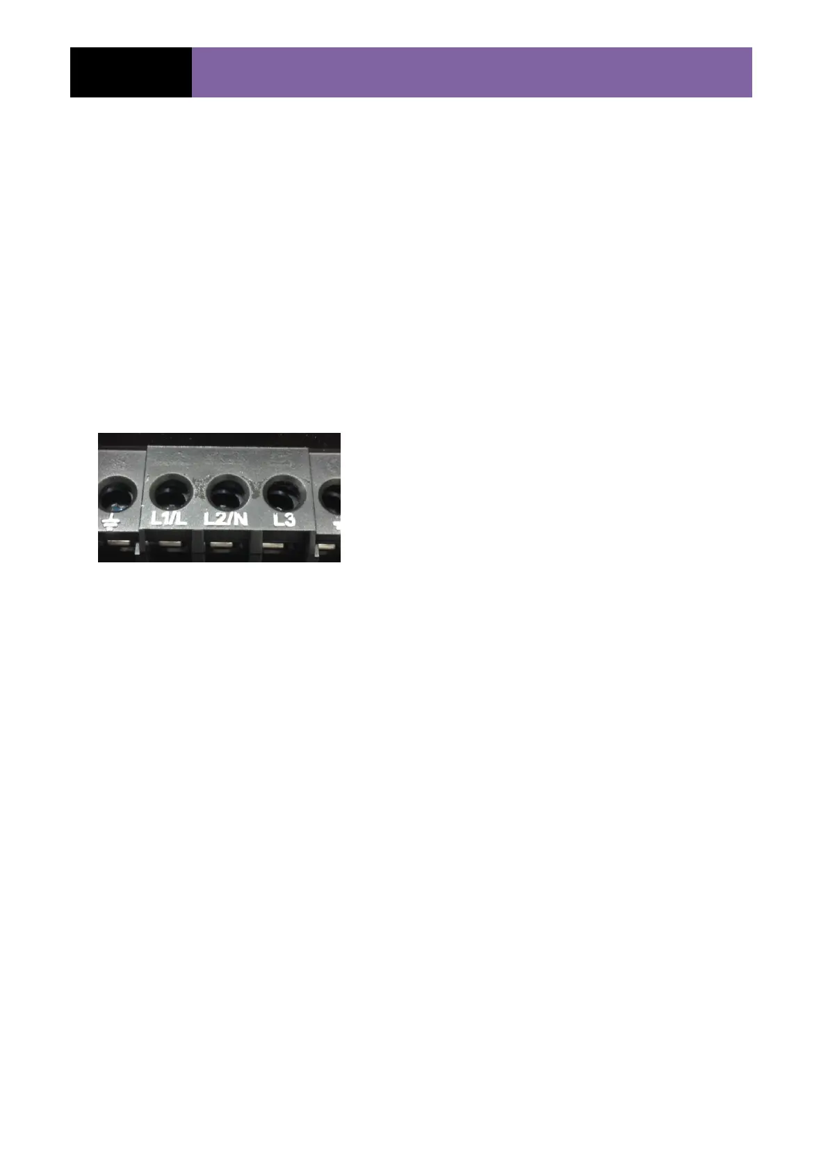
Input Terminal Checks:
Set your multimeter to read Ohms
Place black lead on L1 terminal phase then the red lead on the following
terminals:
L1 to L2 500K +/- 10% and rising
L2 to L3 500K +/- 10% and rising
L1 to L3 500K +/- 10% and rising
Ensure measurement is balanced/same value across each phase
IP66 used control terminal used
as an example

Other manuals for Invertek Drives OPTIDRIVE E3

Questions and Answers:

Question and Answer IconNeed help?

Do you have a question about the Invertek Drives OPTIDRIVE E3 and is the answer not in the manual?

Invertek Drives OPTIDRIVE E3 Specifications

General IconGeneral
BrandInvertek Drives
ModelOPTIDRIVE E3
CategoryDC Drives
LanguageEnglish

Related product manuals