SERVICE MANUAL ODE-3 FRAME SIZE 3
Page 7 of 23
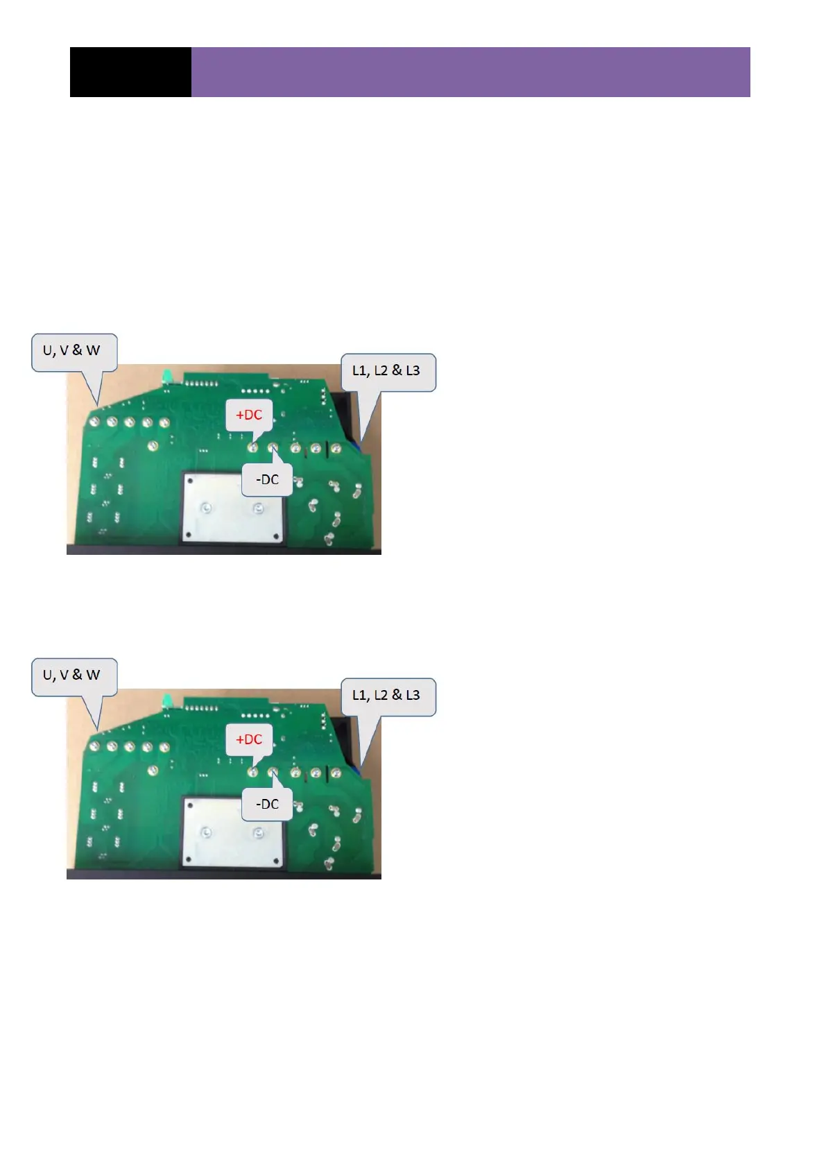
IGBT tests (240V)
Remove cover off drive per the Mechanical Service Manual
In order to carry out the next set of tests the multimeter leads must be placed on the0 +/- DC
Bus in the following steps. (Ensure Multimeter is set to read/test diode)
Rectifier check (L1, L2 & L3)
Using a multimeter set to read diode
complete the following tests:
1) Black lead on the - DC Bus and measure with the
red lead on L1 & L2 input phases, value should read
open circuit.
2) Black lead to +DC point and measure to L1 & L2
Values = 0.52V +/- 10%
3) Red lead on –DC and measure with the black lead
to L1, L2 & L3. Values = 0.521V +/- 10%
4) Red lead on +DC and measure with the black lead
to L1, L2 & L3. values = open circuit.
Output check (U, V & W)
Using a multimeter set to read diode,
complete the following tests:
1) Black lead on the - DC Bus and measure with the
red lead on U, V & W input phases, value should
read open circuit.
2) Black lead on the +DC point and measure to U, V
& W, values = 0.433V +/- 10%
3) Red lead on –DC and measure with the black
lead to L1 U, V & W values = 0.433V +/- 10%
4) Red lead on +DC and measure with the black
lead to U, V & W value should read open circuit.