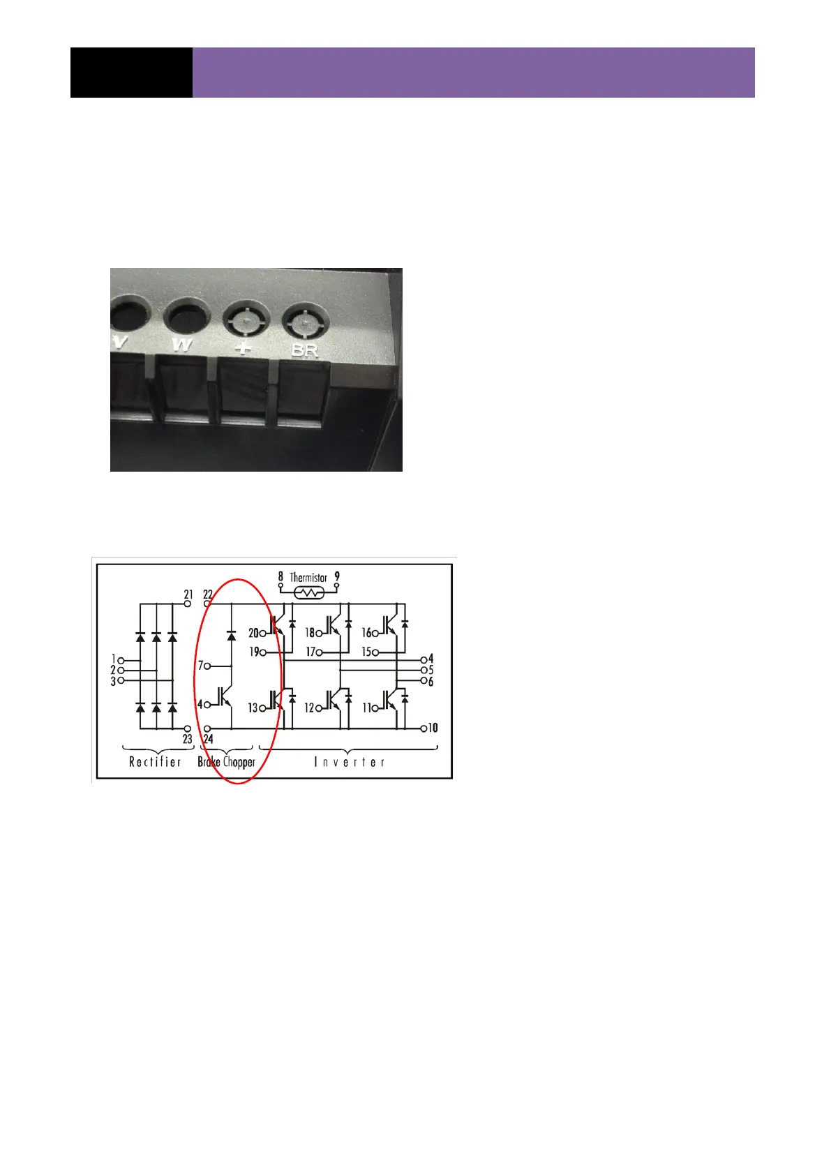
Brake Chopper
The brake chopper circuit is a
means of dumping excess voltage
on the DC Bus.
This excess voltage can be created
when an AC motor is decelerated at
too fast a deceleration ramp time.
The motor will effectively turn into a
generator and will feed a voltage
back into the drive causing the DC
Bus voltage to rise beyond its
nominal value.
To remove excess voltage the drive
can be fitted with a brake resistor
and the voltage can be dissipated in
the form of heat.
Test
As per the diagram opposite the
brake chopper circuit can be tested
using the following multimeter
checks.
Diode test
Set your multimeter to read diode
and carry out the following tests:
Red lead on + terminal/Black
lead on BR terminal = open
circuit
Black lead on + terminal/Red
lead on BR terminal = 0.432V +/-
10%
 Loading...


