Goodrive300-LIFT series inverter Expansion cards
-139-
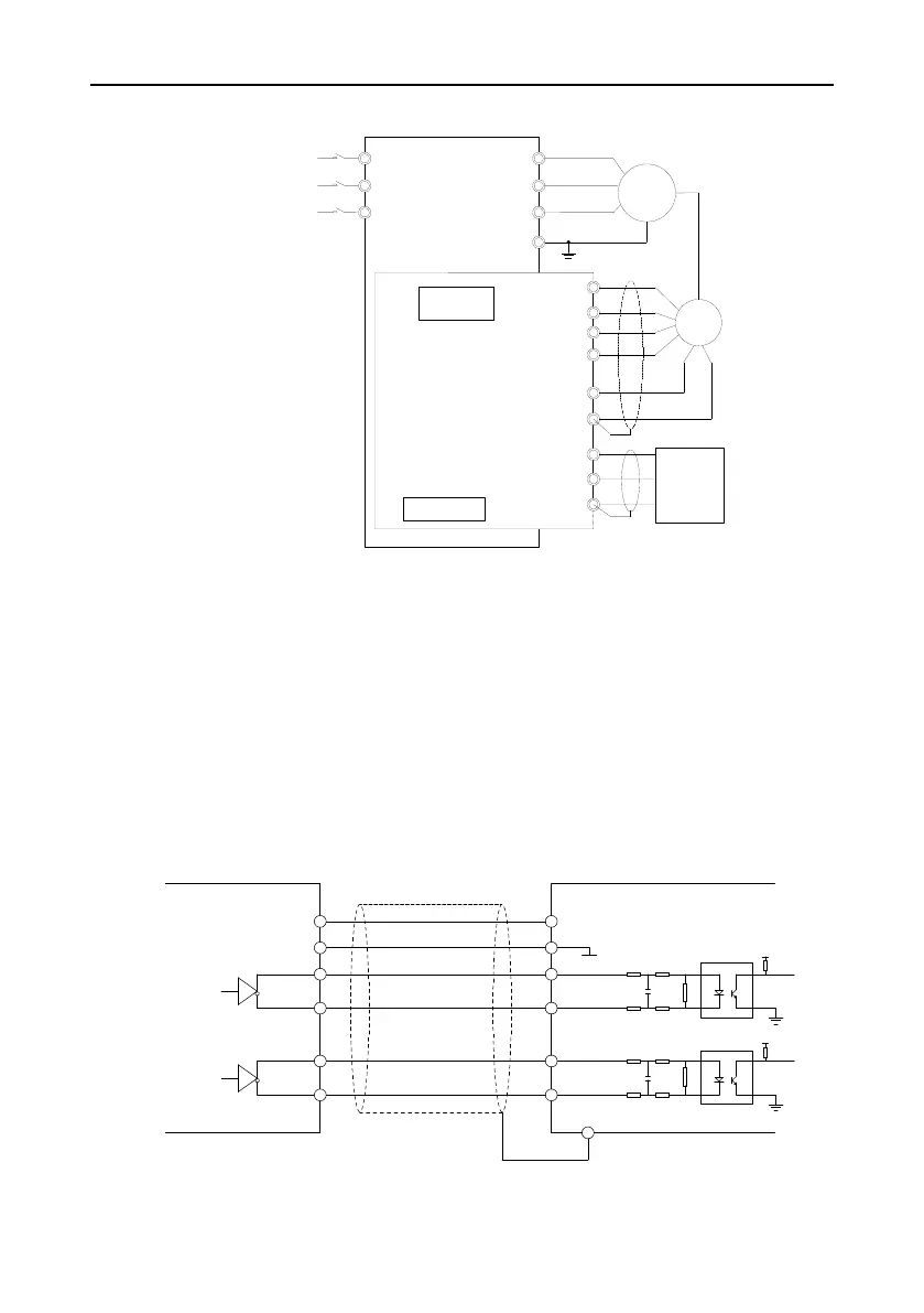
A.3.2.3 Wiring diagram
T
S
R
U
V
W
PE
Potentiometer
Frequency-division
DIP switch
TERA+
+12V
COM1
TER-OA
TERA-
TERB+
TERB-
TER-OB
COM1
36000
RPM
meter
PG
M
Power supply
AC 3PH 380V
50/60Hz
R
S
T
Figure A-6 Wiring diagram of the asynchronous PG card
A.3.2.4 Wiring precautions
The signal wire of the PG card should be routed separately from the power lines.
Please select the shield cables as the PG signal wire for the avoidance of encoder signal.
The shield layer of the encoder cables should be founded with one end (for example, the PE end of
the inverter) for the avoidance of the signal interference.
If the frequency division output of the PG card is connected with the user power supply, the voltage is
less than 24V, otherwise, the PG card may be damaged.
A.3.3 Application connection
(1) Wiring diagram of differential output encoder
B+
A+
TERB
-
TERB
+
TERA
-
TERA
+
COM1
+12V
PE
VCC
0 V
A-
B-
+3.3V
A
B
PG Card
Use shield cable
Differential
output encoder
+3.3V
Figure A-7 Wiring diagram of differential output encoder

 Loading...
