Goodrive300-LIFT series inverter Function parameters
-39-
Detailed instruction of parameters
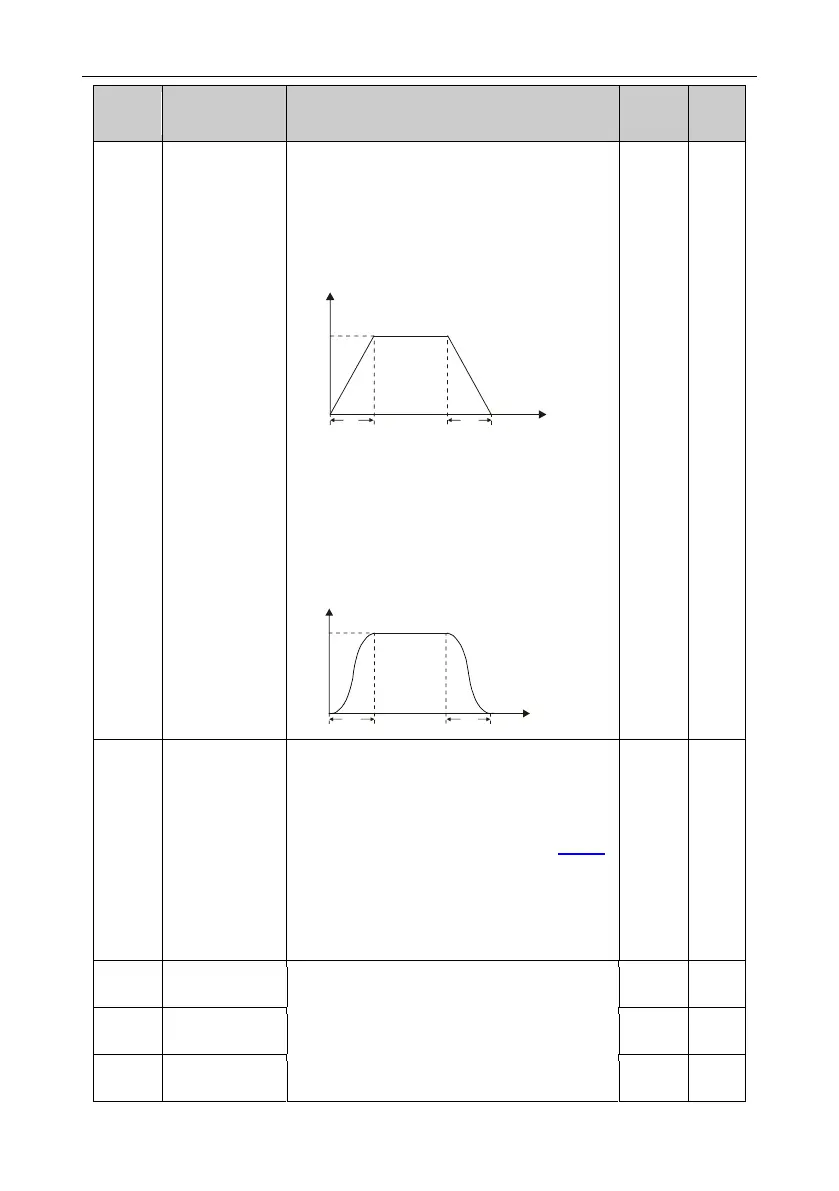
Changing mode of the frequency during start-up
and running.
0: Linear type
The output frequency increases or decreases
linearly.
f
max
Output frequency (f)
t1 t2
Time (t)
1: S curve, indicating the output frequency
increases or decreases according to the S
curve.
Generally, S curve is used in scenarios such as
lifts and conveyers which require smooth startup
and stop.
Output frequency (f)
Time (t)
f
max
t1 t2
0: Decelerate to stop. After the stop command
becomes valid, the inverter decelerates to
decrease the output frequency during the set
time. When the frequency decreases to P01.15,
the inverter stops.
1: Coast to stop: after the stop command
becomes valid, the inverter ceases the output
immediately. And the load coasts to stop at the
mechanical inertia.
Start frequency
in stop braking
Starting frequency of stop braking: The inverter
will carry on stop DC braking when the
frequency is arrived during decelerating to stop.
Demagnetizing time: Before the stop DC

 Loading...
