EasyManua.ls Logo

INVT Goodrive200A Series User Manual

INVT Goodrive200A Series
182 pages
To Next Page IconTo Next Page
To Previous Page IconTo Previous Page
Page #45 background imageLoading...
Page #45 background image
GD200A series VFD Function parameters
-38-
Function
code
Name
Description
Default
value
Modify
P00.11
ACC time 1
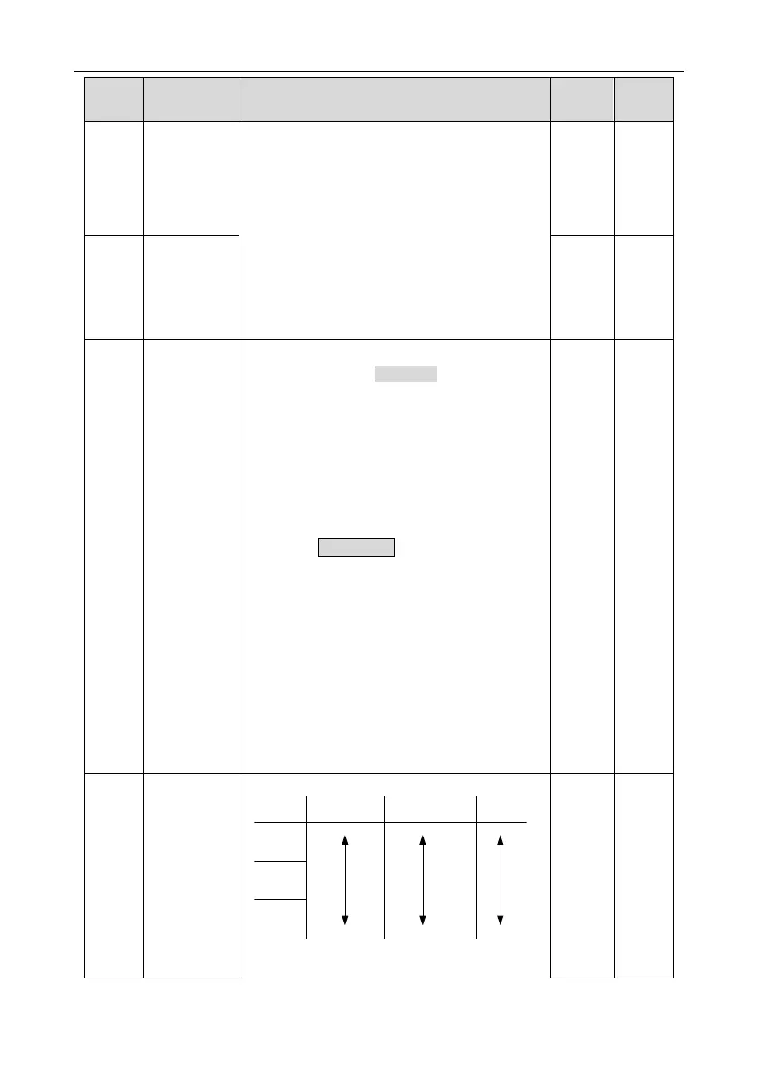
ACC time means the time needed if the VFD
speeds up from 0Hz to the max. one (P00.03).
DEC time means the time needed if the VFD
speeds down from the max. output frequency to
0Hz (P00.03).
Goodrive200A series VFDs define four groups of
ACC/DEC time which can be selected by P05.
The factory default ACC/DEC time of the VFD is
the first group.
Setting range of P00.11 and P00.12: 0.03600.0s
Depend
on
model
P00.12
DEC time 1
Depend
on
model
P00.13
Running
direction
0: Runs at the default direction, the VFD runs in
the forward direction. FWD/REV indicator is off.
1: Runs at the opposite direction, the VFD runs in
the reverse direction. FWD/REV indicator is on.
Modify the function code to shift the rotation
direction of the motor. This effect equals to the
shifting the rotation direction by adjusting either
two of the motor lines (U, V and W). In keypad
control, the motor rotation direction can be
changed by QUICK/JOG on the keypad. Refer to
parameter P07.02.
Note: When the function parameter comes back
to the default value, the motor’s running direction
will come back to the factory default state, too. In
some cases it should be used with caution after
commissioning if the change of rotation direction is
disabled.
2: Forbid to run in reverse direction: It can be used
in some special cases if the reverse running is
disabled.
0
P00.14
Carrier
frequency
setting
Carrier
frequency
Electro magnetic
noise
Noise and leakage
current
Heating
eliminating
High
LowHigh
Low
High
Low
1kHz
10kHz
15kHz
Mapping between models and carrier frequencies:
Depend
on
model

Table of Contents

Question and Answer IconNeed help?

Do you have a question about the INVT Goodrive200A Series and is the answer not in the manual?

INVT Goodrive200A Series Specifications

General IconGeneral
BrandINVT
ModelGoodrive200A Series
CategoryDC Drives
LanguageEnglish

Summary

Preface

Safety Definition

Defines terms like Danger, Warning, and Note for safety communication.

Warning Symbols

Explains symbols used for warnings: Danger, Warning, Do not touch, Hot.

Safety Precautions

Safety Definition

Defines terms like Danger, Warning, and Note for safety communication.

Warning Symbols

Explains symbols used for warnings: Danger, Warning, Do not touch, Hot.

Safety Guidelines

Delivery and Installation Safety

Guidelines for safe delivery, handling, and installation of the VFD.

Commissioning and Running Safety

Maintenance and Component Replacement Safety

Scrap Treatment and Disposal

Quick Start Guide

Unpacking and Initial Inspection

Steps to check the VFD and its accessories after receiving the product.

Application Confirmation

Checks to perform on the load and supply voltage before VFD use.

Installation Environment Requirements

Specifies conditions for ambient temperature, humidity, altitude.

Installation Confirmation

Basic Commissioning Procedures

Product Overview

Basic Principles of VFD Operation

Explains the VFD's rectifier, DC bus, and converter functions.

Product Specifications

Nameplate Information

Type Designation Key

Rated Specifications Summary

VFD Structure Diagram

Installation Guidelines

Mechanical Installation

Covers VFD mounting, orientation, and environment.

Standard Wiring Practices

Details main circuit, control circuit, and I/O wiring.

Layout Protection Measures

Covers protection against short circuits, overload, and interference.

Keypad Operation Procedure

Keypad Overview and Components

Identifies VFD keypad models and their components.

Keypad Display and Basic Operation

Explains VFD display states and basic keypad interactions.

Modifying Function Codes

Setting the VFD Password

Watching VFD State via Function Codes

Function Parameters

General Series Function Parameters

Overview of parameter groups (P00-P29) and their structure.

Protective Parameters

Basic Operation Instruction

First Powering On Procedure

Steps for initial VFD power-up and initialization.

Vector Control Explained

Details the principles and application of vector control for motors.

Torque Control Explained

Explains torque control mode and its relation to speed control.

Motor Parameter Setup Guide

Instructions for setting motor parameters and performing autotune.

Start and Stop Control

Describes VFD start/stop methods and logic diagrams.

Frequency Setting Methods

Explains various ways to set VFD frequency reference.

Simple PLC Functionality

Multi-step Speed Running

PID Control Explained

PID Control Overview

Introduction to PID control for process regulation.

PID Parameter Setting Steps

Guide to setting PID parameters (P, Ti, Td) for optimal control.

Fault Tracking and Troubleshooting

Alarm and Fault Indications

How VFD alarms and faults are indicated via LEDs and display.

Fault Instruction and Solution Guide

Lists fault codes, types, possible causes, and corrective actions.

Common Fault Analysis

Diagnostic flowcharts for common VFD faults.

VFD System Interference Troubleshooting

Methods to identify and mitigate VFD system interference.

Maintenance and Hardware Diagnostics

Procedures for routine VFD inspection and diagnostics.

Cooling Fan Maintenance and Replacement

Capacitor Reforming Procedure

Communication Protocol

MODBUS Protocol Overview

Introduction to MODBUS protocol and its application in VFDs.

RS485 and RTU Mode Application

Details on RS485 interface and RTU communication mode.

Communication Command Examples

Examples of reading and writing commands via RTU and ASCII.

Data Address Definition in MODBUS

Mapping of VFD parameters to MODBUS addresses.

Fault Message Responses in Communication

Explains VFD fault messages returned during communication.

Appendix A: Technical Data

VFD Ratings and Capacity Specifications

Details VFD power, current, voltage, and frequency ratings.

Derating Factors for VFD Operation

Information on derating due to temperature, altitude, and carrier frequency.

EMC Compatibility and Applicable Standards

Details EMC requirements and relevant industry standards.

Appendix B: Dimension Drawings

Keypad Structure and Installation Details

Shows keypad dimensions and mounting options.

VFD Wall Mounting Dimensions

Provides dimensions and mounting hole details for wall installation.

VFD Flange Mounting Dimensions

Details dimensions and mounting hole specifications for flange installation.

VFD Floor Mounting Dimensions

Provides dimensions and mounting details for floor installation.

Appendix C: Peripheral Options and Parts

Peripheral Wiring Overview

Illustrates typical peripheral connections for the VFD.

Power Cables and Control Cables

Details recommended cable types, sizes, and installation.

Breakers and Protection Devices

Guidance on selecting protective devices like breakers and contactors.

Reactors and Filters Selection

Information on selecting appropriate reactors and filters for the VFD.

Braking System Component Selection

Guidance on selecting braking resistors and units.

Other Optional Parts and Accessories

Lists optional parts like side covers, keypads, and installation brackets.

Appendix D: Further Information

Product and Service Inquiries

Contact information for product and service inquiries.

Manual Feedback and Online Resources

Information on providing feedback and accessing online documentation.

Related product manuals