GD200A series VFD Function parameters
-58-
Set the bit to 1, the input terminal is cathode.
The setting range: 0x000–0x1FF
Set the sample filter time of S1–S8 and HDI
terminals. If the interference is strong, increase
the parameter to avoid the disoperation.
0.000–1.000s
Virtual
terminals
setting
0x000–0x1FF(0: Disabled, 1: Enabled )
BIT0: S1 virtual terminal
BIT1: S2 virtual terminal
BIT2: S3 virtual terminal
BIT3: S4 virtual terminal
BIT4: S5 virtual terminal
BIT5: S6 virtual terminal
BIT6: S7 virtual terminal
BIT7: S8 virtual terminal
BIT8: HDI virtual terminal
Note: After a virtual terminal is enabled, the
terminal status can be changed only through
communication, and the communication address
is 0x200A.
Terminals
control running
mode
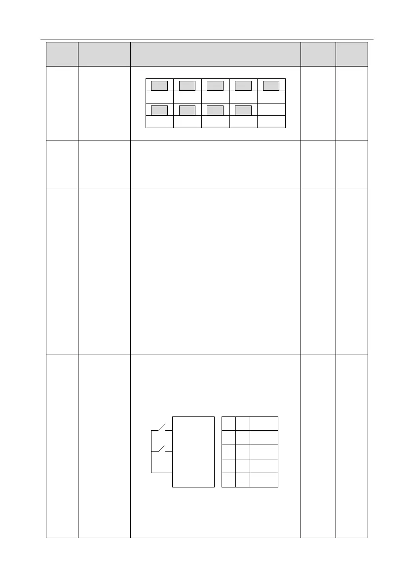
Set the operation mode of the terminals control
0: 2-wire control 1, comply the enable with the
direction. This mode is widely used. It determines
the rotation direction by the defined FWD and
REV terminals command.
FWD
REV
COM
K1
K2
Running
command
FWD REV
OFF OFF
OFF
OFF
ON
ON
ON ON
Stopping
Hold on
Forward
running
Reverse
running
1: 2-wire control 2; Separate the enable from the
direction. FWD defined by this mode is the
enabling ones. The direction depends on the state
of the defined REV.

 Loading...


