Goodrive350 series high-performance multi-function inverter Chapter 3
-8-
Chapter 3 Product overview
3.1 What this chapter contains
This chapter mainly introduces the operation principles, product features, layouts, nameplates and
model instructions.
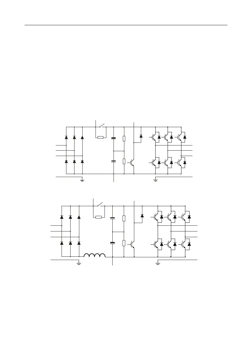
3.2 Basic principle
Goodrive350 series inverter is used to control asynchronous AC induction motor and
permanent-magnet synchronous motor. The figure below shows the main circuit diagram of the
inverter. The rectifier converts 3PH AC voltage into DC voltage, and the capacitor bank of
intermediate circuit stabilizes the DC voltage. The inverter converts DC voltage into the AC voltage
used by AC motor. When the circuit voltage exceeds the max. limit value, external brake resistor will
be connected to intermediate DC circuit to consume the feedback energy.
Fig 3.1 380V (15kW and below) main circuit diagram
Fig 3.2 380V (18.5kW–110kW (inclusive) ) main circuit diagram

 Loading...


