Goodrive350 series high-performance multi-function inverter Appendix A
-278-
A.5 PG extension card function description
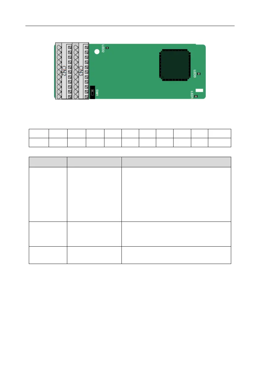
A.5.1 Multi-function incremental PG card––EC-PG505-12
The terminals are arranged as follows:
The dual in-line package (DIP) switch SW1 is used to set the voltage class (5 V or 12 V) of the power
supply of the encoder. The DIP switch can be operated with an auxiliary tool.
Indicator definition
This indicator is on when the extension card is
establishing a connection with the control board; it
blinks periodically after the extension card is
properly connected to the control board (the
period is 1s, on for 0.5s, and off for the other 0.5s);
and it is off when the extension card is
disconnected from the control board.
This indicator is off when A1 and B1 of the
encoder is disconnected; and it is on when the
pulses are normal.
This indicator is on after the control board feeds
power to the PG card.
The EC-PG505-12 extension card can be used in combination with multiple types of incremental
encoders through different modes of wiring. It is user-friendly, adopting spring terminals.

 Loading...
