Goodrive350 series high-performance multi-function inverter Appendix A
-276-
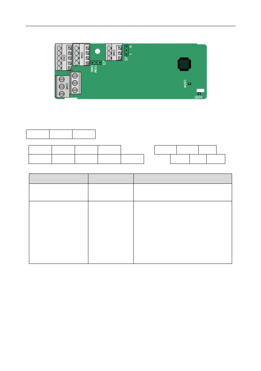
A.4 IO extension card function description
A.4.1 IO extension card––EC-IO501-00
The terminals are arranged as follows:
CME and COM are shorted through J3 before delivery, and J5 is the jumper for selecting the output
type (voltage or current) of AO2.
Indicator definition
This indicator is on after the IO extension
card is powered on by the control board.
This indicator is on when the extension card
is establishing a connection with the control
board; it blinks periodically after the
extension card is properly connected to the
control board (the period is 1s, on for 0.5s,
and off for the other 0.5s); and it is off when
the extension card is disconnected from the
control board.
The EC-IO501-00 extension card can be used in scenarios where the I/O interfaces of a Goodrive350
inverter cannot meet the application requirements. It can provide 4 digital inputs, 1 digital output, 1
analog input, 1 analog output, and two relay outputs. It is user-friendly, providing relay outputs
through European-type screw terminals and other inputs and outputs through spring terminals.
EC-IO501-00 terminal function description

 Loading...


