Goodrive350 series high-performance multi-function inverter Chapter 4
-31-
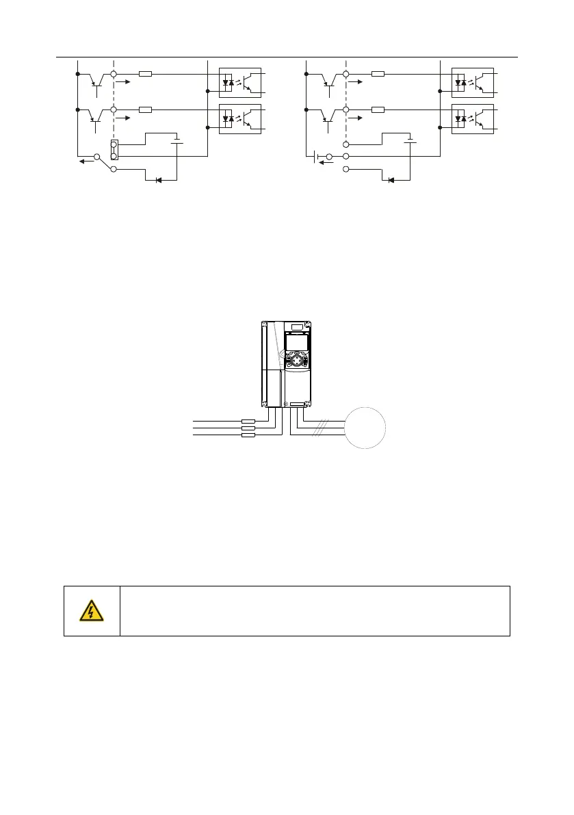
S1
S2
COM
PW
+ 24V
COM
+ 24V
External power(PNP mode)
S1
S2
COM
PW
+ 24V
COM
+ 24V
Internal power(PNP mode)
Fig 4.21 PNP mode
4.5 Wiring protection
4.5.1 Protect the inverter and input power cable in short-circuit
Protect the inverter and input power cable during short-circuit to avoid thermal overload.
Carry out protective measures according to the following requirements.
Input cable
Inverter
M3
~
Fuse
Fig 4.22 Fuse configuration
Note: Select the fuse according to operation manual. During short-circuit, the fuse will protect
input power cables to avoid damage to the inverter; when internal short-circuit occurred to the
inverter, it can protect neighboring equipment from being damaged.
4.5.2 Protect the motor and motor cable in short circuit
If the motor cable is selected based on rated inverter current, the inverter will be able to protect the
motor cable and motor during short circuit without other protective devices.
If the inverter is connected to multiple motors, it is a must to use a separated
thermal overload switch or breaker to protect the cable and motor, which may
require the fuse to cut off the short circuit current.
4.5.3 Protect motor and prevent thermal overload
According to the requirements, the motor must be protected to prevent thermal overload. Once
overload is detected, users must cut off the current. The inverter is equipped with motor thermal
overload protection function, which will block output and cut off the current (if necessary) to protect
the motor.

 Loading...


