Goodrive350 series high-performance multi-function inverter Appendix E
-333-
E.2 STO channel delay description
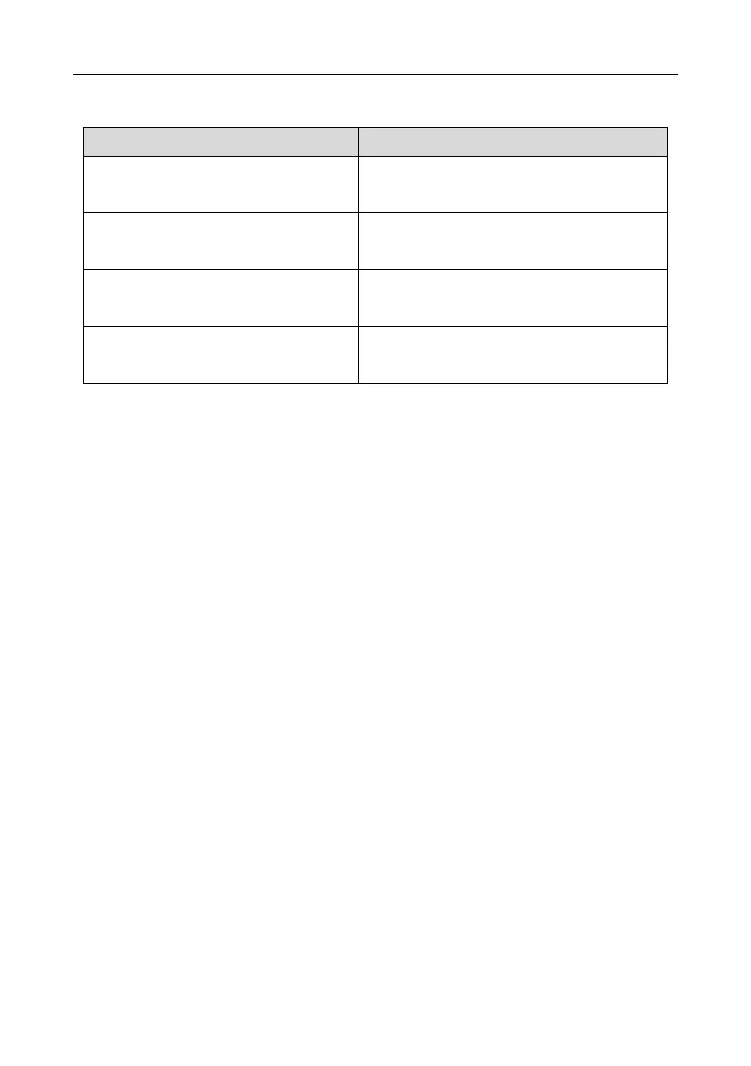
The following table describes the trigger and indication delay of the STO channels.
STO trigger and indication delay
1, 2
Trigger delay < 10 ms
Indication delay < 280 ms
Trigger delay < 10 ms
Indication delay < 280 ms
Trigger delay < 10 ms
Indication delay < 280 ms
Trigger delay < 10 ms
Indication delay < 100 ms
1. STO function trigger delay: Time interval between trigger the STO function and switching off the
drive output
2. STO instruction delay: Time interval between trigger the STO function and STO output state
indication

 Loading...


