Goodrive350 series high-performance multi-function inverter Chapter 4
-28-
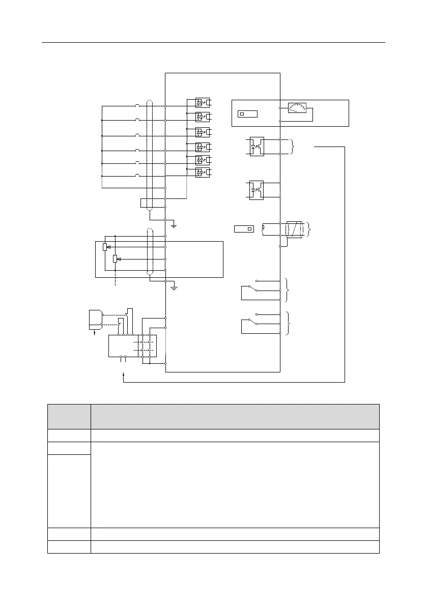
4.4 Standard wiring of control circuit
4.4.1 Wiring diagram of basic control circuit
+24V
PE
COM
S4
S3
S2
S1
HDIB
PW
HDIA
Forward running
Jogging
Fault reset
+10V
AI1
AI2
GND
PE
-10V
(external)
Goodrive350 series
inverter
A01
V I
SW2
GND
Analog output
0-10V/0-20mA
Y1
CME
COM
HDO
Optional between high-
speed pulse output and
open collector output
485+
485-
485G
RS485
communication
RO2C
RO2B
RO2A
RO1C
RO1B
RO1A
Relay 1
output
Relay 2
output
ON
OFF
SW3
multi-function
analog input
power used for
frequency setting
H1
H2
+24V
S2
S1
Safety
controller
Open circuit
Safety
input
Safety
switch
Y1
output
Safety state
feedback
Fig 4.18 Wiring diagram of control circuit
The inverter provides +10.5V power
1. Input range: AI1 voltage/current can choose 0–10/ 0–20mA;
AI2: -10V–+10V voltage;
2. Input impedance: 20kΩ during voltage input; 250Ω during current input;
3. AI1 voltage or current input is set by P05.50;
4. Resolution ratio: When 10V corresponds to 50Hz, the min. resolution ratio is
5mV;
5. 25°C , When input above 5V or 10mA, the error is ±0.5%
+10.5V reference zero potential
1. Output range: 0–10V voltage or 0–20mA current

 Loading...


